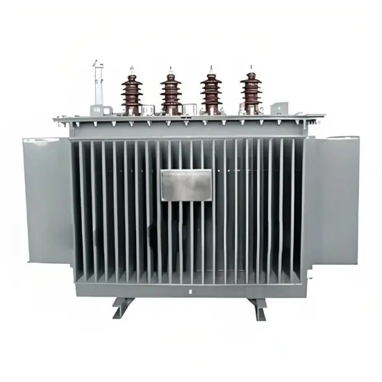
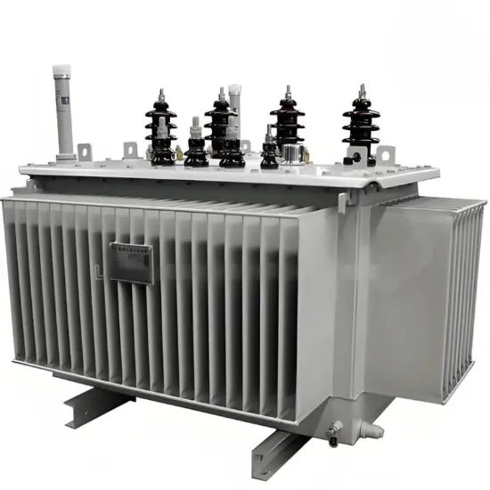
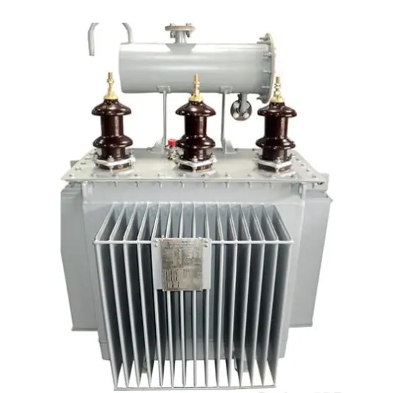
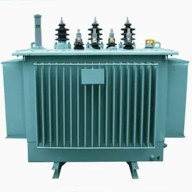
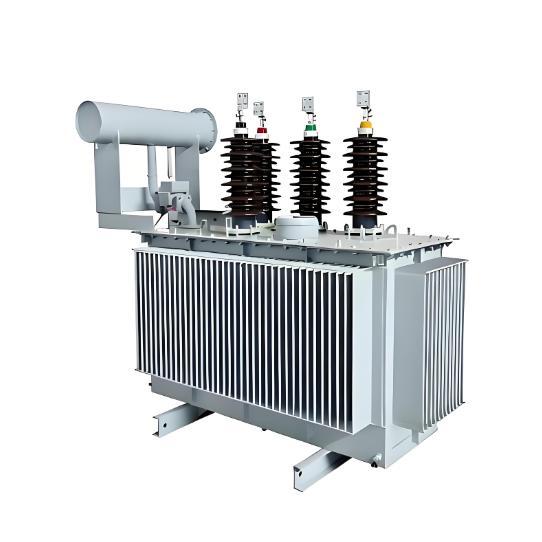
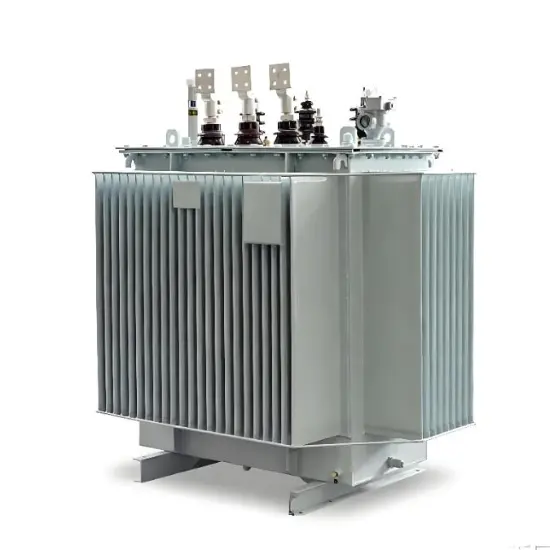
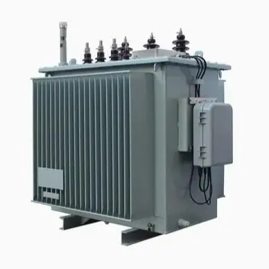
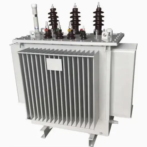
Zig-zag Oil immersed earthing transformer 15kV 17.5kV 20kV
Key attributes
| Brand | Vziman |
| Model NO. | Zig-zag Oil immersed earthing transformer 15kV 17.5kV 20kV |
| Rated voltage | 15kV |
| Rated frequency | 50Hz |
| Series | S |
Product descriptions from the supplier
Description
Summary
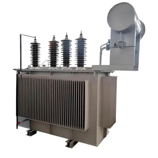
Our Oil immersed earthing transformer, including Zig-zag Earthing Transformer, adopts insulating fluid immersion and natural self-cooling (ONAN) mode, three-phase design, and 50/60 Hz frequency. Suitable for indoor and outdoor use, it features hermetic sealing, CRGO silicon steel core, and high-strength cold-rolled steel tank, ensuring stable grounding protection performance.
Features
- Power Ratings & Voltage : Common power ratings for Oil immersed earthing transformer (including Zig-zag Earthing Transformer) are 30–2500 kVA, for voltages ≤ 36 kV. Dual primary voltages (via no-load tap changer/terminal adjustment) and secondary voltages (400V/415V/433V, customizable) are available.
- Connection Configurations:Standard connections for Zig-zag Earthing Transformer and Oil immersed earthing transformer are Yyn0 (≤160 kVA) and Dyn11 (>160 kVA); other configurations are customizable.
- Temperature Rise : Per IEC/BSEN 60076, Oil immersed earthing transformer has max oil temp rise 60K, winding avg 65K; Zig-zag Earthing Transformer allows custom temp rise.
- Oil Expansion System:Oil immersed earthing transformer (including Zig-zag Earthing Transformer) has three oil expansion systems; Vziman recommends hermetic elastic tanks for compactness and low maintenance.
| Material maximum admissible voltage | 12kV | 17.5kV | 24kV | 36kV |
| Withstand voltage | 28kV | 38kV | 50kV | 70kV |
| Basic insulation level | 75kV | 95kV | 125kV | 170kV |
Highest voltage for material: ≤ 12 kV
| Rated capacity (kVA) | HV(kV) | Tapping range | LV (kV) | Vector group | Loss(kW) | No-load current (%) | Impedance voltage (%) | Weight (kg) | ||
| Load loss | No-load loss | oil | Total | |||||||
| 10 |
6 10 11 |
±5% or ±2*2.5% |
0.4 0.415 0.433 |
Dyn11 or Yyn0 |
0.26 | 0.09 | 3.2 | 4 | 45 | 172 |
| 20 | 0.44 | 0.10 | 3.0 | 65 | 240 | |||||
| 30 | 0.63 | 0.13 | 2.3 | 65 | 245 | |||||
| 50 | 0.91 | 0.17 | 2.0 | 80 | 330 | |||||
| 63 | 1.09 | 0.20 | 1.9 | 90 | 365 | |||||
| 80 | 1.31 | 0.25 | 1.9 | 95 | 410 | |||||
| 100 | 1.58 | 0.29 | 1.8 | 115 | 490 | |||||
| 125 | 1.89 | 0.34 | 1.7 | 140 | 620 | |||||
| 160 | 2.31 | 0.40 | 1.6 | 155 | 720 | |||||
| 200 | 2.73 | 0.48 | 1.5 | 175 | 810 | |||||
| 250 | 3.20 | 0.56 | 1.4 | 200 | 940 | |||||
| 315 | 3.85 | 0.67 | 1.4 | 215 | 1090 | |||||
| 400 | 4.52 | 0.80 | 1.3 | 240 | 1250 | |||||
| 500 | 5.41 | 0.96 | 1.2 | 285 | 1460 | |||||
| 630 | 6.20 | 1.20 | 1.1 | 4.5 | 345 | 1720 | ||||
| 800 | 7.50 | 1.40 | 1.1 | 390 | 2050 | |||||
| 1000 | 10.30 | 1.70 | 1.0 | 460 | 2430 | |||||
| 1250 | 12.00 | 1.95 | 1.0 | 550 | 2850 | |||||
| 1600 | 14.50 | 2.40 | 0.8 | 690 | 3600 | |||||
| 2000 | 18.00 | 2.60 | 0.7 | 790 | 4300 | |||||
Highest voltage for material: 15-24 kV
| Rated capacity (kVA) | HV(kV) | Tapping range | LV (kV) | Vector group | Loss(kW) | No-load current (%) | Impedance voltage (%) | Weight (kg) | ||
| Load loss | No-load loss | oil | Total | |||||||
| 30 |
15 20 |
±5% or ±2*2.5% |
0.4 0.415 0.433 |
Dyn11 or Yyn0 |
0.60 | 0.10 | 2.1 | 4 | 85 | 350 |
| 50 | 0.87 | 0.13 | 2.0 | 90 | 480 | |||||
| 63 | 1.04 | 0.15 | 1.9 | 110 | 600 | |||||
| 80 | 1.25 | 0.18 | 1.8 | 110 | 660 | |||||
| 100 | 1.50 | 0.20 | 1.6 | 120 | 700 | |||||
| 125 | 1.80 | 0.24 | 1.5 | 130 | 800 | |||||
| 160 | 2.20 | 0.29 | 1.4 | 140 | 940 | |||||
| 200 | 2.60 | 0.33 | 1.2 | 160 | 1130 | |||||
| 250 | 3.05 | 0.40 | 1.2 | 180 | 1290 | |||||
| 315 | 3.65 | 0.48 | 1.1 | 230 | 1400 | |||||
| 400 | 4.30 | 0.57 | 1.0 | 250 | 1550 | |||||
| 500 | 5.15 | 0.68 | 1.0 | 260 | 1780 | |||||
| 630 | 6.20 | 0.81 | 0.9 | 320 | 2100 | |||||
| 800 | 7.50 | 0.98 | 0.8 | 350 | 2560 | |||||
| 1000 | 10.30 | 1.15 | 0.7 | 4.5 | 450 | 2800 | ||||
| 1250 | 12.00 | 1.36 | 0.6 | 490 | 3200 | |||||
| 1600 | 14.50 | 1.64 | 0.6 | 640 | 4000 | |||||
| 2000 | 17.14 | 1.94 | 0.6 | 800 | 4900 | |||||
| 2500 | 20.26 | 2.30 | 0.5 | 1180 | 6300 | |||||
Highest voltage for material: 36 kV
| Rated capacity (kVA) | HV(kV) | Tapping range | LV (kV) | Vector group | Loss(kW) | No-load current (%) | Impedance voltage (%) | Weight (kg) | ||
| Load loss | No-load loss | oil | Total | |||||||
| 50 |
30 33 35 38.5 |
±5% or ±2*2.5% |
0.4 0.415 0.433 |
Dyn11 Yyn0 Yd11 |
1.27 | 0.21 | 2.0 | 4 | 265 | 860 |
| 100 | 2.12 | 0.29 | 1.8 | 310 | 1150 | |||||
| 125 | 2.50 | 0.34 | 1.7 | 320 | 1190 | |||||
| 160 | 2.97 | 0.36 | 1.6 | 360 | 1230 | |||||
| 200 | 3.50 | 0.43 | 1.5 | 390 | 1300 | |||||
| 250 | 4.16 | 0.51 | 1.4 | 425 | 1480 | |||||
| 315 | 5.01 | 0.61 | 1.4 | 460 | 1590 | |||||
| 400 | 6.05 | 0.73 | 1.3 | 490 | 1760 | |||||
| 500 | 7.28 | 0.86 | 1.2 | 540 | 2150 | |||||
| 630 | 8.28 | 1.04 | 1.1 | 620 | 2380 | |||||
| 800 | 9.90 | 1.23 | 1.0 | 780 | 2800 | |||||
| 1000 | 12.15 | 1.44 | 1.0 | 850 | 3410 | |||||
| 1250 | 14.67 | 1.76 | 0.9 | 950 | 3890 | |||||
| 1600 | 17.55 | 2.12 | 0.8 | 1060 | 4620 | |||||
| 2000 | 19.35 | 2.72 | 0.7 | 4.5 | 1195 | 5345 | ||||
| 2500 | 20.70 | 3.20 | 0.6 | 1285 | 5960 | |||||
| 3150 | 24.30 | 3.80 | 0.6 | 1470 | 6695 | |||||
| 4000 | 28.80 | 4.52 | 0.5 | 1760 | 8350 | |||||
Standard
Both Zig-zag Earthing Transformer andOil immersed earthing transformer are designed and tested in strict accordance with IEC/BSEN 60076 standards, meeting international requirements for earthing transformer performance and safety.
Construction Details
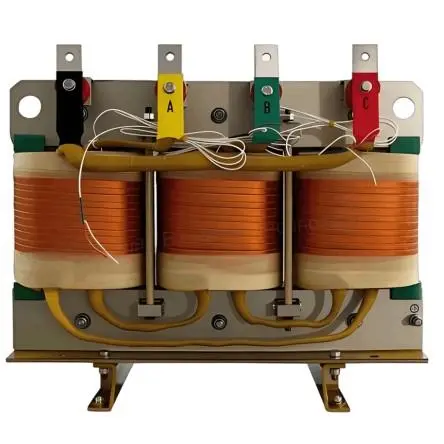
- Magnetic Circuit :The magnetic circuit of Zig-zag Earthing Transformer and Oil immersed earthing transformer uses low-loss oriented plates (IEC/BSEN 60076), with 45° joints to minimize gap effects and optimize performance.
- Low Voltage Winding: The low-voltage winding of Oil immersed earthing transformer uses insulated wires/strips, resisting short-circuit stress (IEC 60076) and suiting Zig-zag Earthing Transformer operation.
High Voltage Winding
- English: Wrapped around the low-voltage winding, the high-voltage winding ofZig-zag Earthing Transformer uses circular/rectangular conductors (class H enamel insulation). Anti-resonant section design resists ray-type pulse waves, and resin-impregnated interlayer insulation ensures mechanical strength under short circuits, matching Oil immersed earthing transformer reliability.
- Active Part: The active part of Oil immersed earthing transformer (removable from the tank) includes core, windings, fixing structure, tap changer, cover, and bushings. For Zig-zag Earthing Transformer, the active part is optimized for zero-sequence current conduction, ensuring stable grounding performance.
Tank
The elastic tank of Oil immersed earthing transformer absorbs oil volume expansion without permanent deformation, consisting of supporting frames, base, cooling fins, and outer frame. Corrugated cooling fins (cold-rolled steel) provide elasticity, while watertight welding and pressure limiters enhance leak resistance—ideal for Zig-zag Earthing Transformer outdoor operation.
Documentation Resource Library
Restricted.
Vziman IEC/ ANSI Oil-immersed Grounding Transformer selection catalog
Catalogue
English
Consulting
Related Products
-
250kVA Zig Zag Grounding Transformer by Vziman
-
Oil-immersed Ground Transformer direct supply-10.5kV 35kV
-
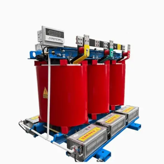
34.5kV Three Phase Dry Type Zig Zag Grounding Transformer
-
Industrial ONAN Earthing Transformers-25.8kV 27kV 33kV

-
315kVA Oil-Immersed Grounding Transformer for Industrial Distribution Network Grounding Protection
-
20kVA 3 Phase Industrial Dry-Type Earthing Transformers
-
Custom electric opper dry-type grounding transformer 6kV 6.3kV 6.6kV
-
Separated Winding Neutral Earthing Transformer 4.16kV 12.47kV 13.2kV
-
34.5kV 35kV 38.5kV Oil-Immersed Grounding Transformer for Industrial Distribution Network Grounding Protection
-
Three Phase Medium Voltage Oil-Immersed Grounding Transformer 10kV 11kV 15kV