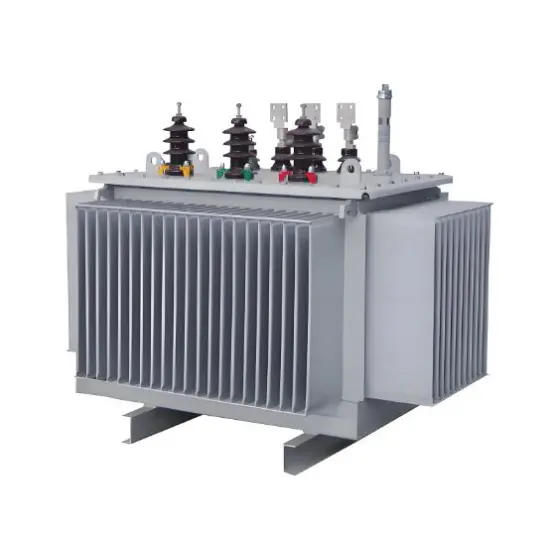
6.3kV 24kV 33kV Fully sealed oil-immersed power distribution transformer
Key attributes
| Brand | Vziman |
| Model NO. | 6.3kV 24kV 33kV Fully sealed oil-immersed power distribution transformer |
| Rated voltage | 6.3kV |
| Rated frequency | 50/60Hz |
| Rated capacity | 600kVA |
| Series | S11 |
Product descriptions from the supplier
Description
Description
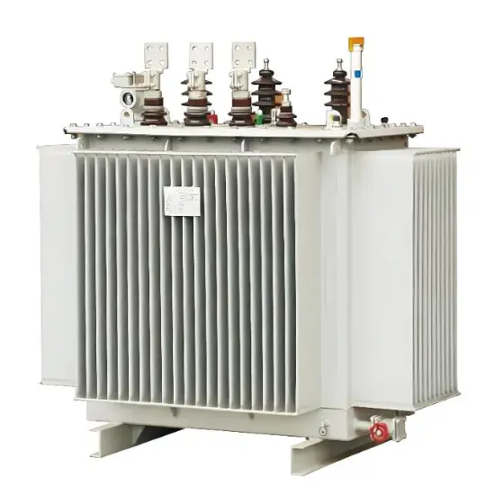
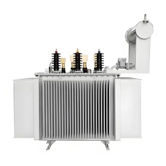
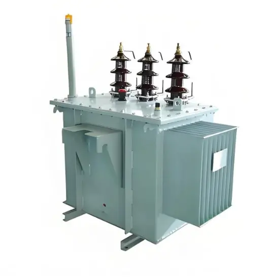
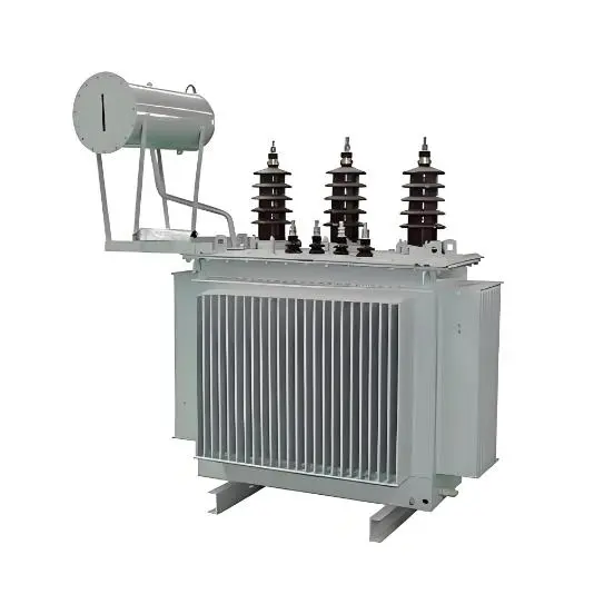
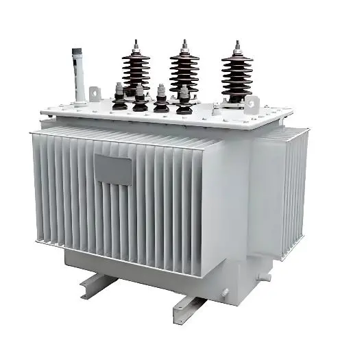
Built for AC 50Hz power systems , these 6.3kV/24kV/33kV S11-M units are ideal distribution transformers for petroleum, metallurgy, chemical, textile, and light industrial facilities—including dust-heavy environments.
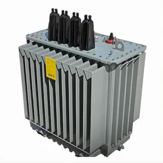
Their fully sealed design prevents oil leaks, blocks dust/moisture, and enables maintenance-free long-term operation. With low loss, low noise, and strong overload capability, they deliver stable power even in harsh conditions, meeting industrial-grade reliability demands.
Feature
- Full Hermetic Sealing Design:Eliminates oil leakage risks and effectively isolates dust, moisture and corrosive gases from the external environment, ensuring stable operation in harsh conditions like dusty industrial workshops.
- Low Loss & High Energy Efficiency:Adopts advanced core and coil structure, significantly reducing no-load and load losses, cutting down long-term energy consumption, and complying with global high-efficiency power equipment standards.
- Wide Application Compatibility:Optimized for AC 50Hz power systems, ideal for petroleum, metallurgy, chemical, textile and light industry sectors, perfectly matching the power distribution needs of special industrial scenarios.
- Low Noise & Maintenance-free Operation:Integrates noise reduction structural design for quiet running; the sealed structure avoids regular oil replacement and maintenance work, lowering the overall operation and maintenance costs.
- Strong Overload & Short-circuit Resistance:Reinforced clamp and frame structure enhances mechanical strength, with excellent overload capacity and short-circuit withstand performance to cope with sudden load fluctuations in industrial grids.
Technical Parameters
| Rated capacity (kVA) |
Voltage combination | The connection group designation number | No-load loss (W) |
Load Loss (W) |
No-load current (%) |
Short Circuit Impedance (%) |
Weight (kg) | |||
| High Voltage (kV) |
High voltage tapping range | Low Voltage (kV) |
oil weight | Total weight | ||||||
| 30 | 6 6.3 6.6 10 10.5 11 |
±5% ±2×2.5% |
0.4 | Yyn0 Dyn11 |
100 | 630/600 | 2.1 | 4 | 75 | 295 |
| 50 | 130 | 910/870 | 1.1 | 88 | 395 | |||||
| 63 | 150 | 1090/1040 | 1 | 95 | 420 | |||||
| 80 | 180 | 1310/1250 | 1 | 103 | 480 | |||||
| 100 | 200 | 1580/1500 | 0.9 | 115 | 540 | |||||
| 125 | 240 | 1890/1800 | 0.9 | 130 | 645 | |||||
| 160 | 280 | 2310/220 | 0.8 | 145 | 740 | |||||
| 200 | 340 | 2730/2600 | 0.8 | 175 | 885 | |||||
| 250 | 400 | 3200/3050 | 0.7 | 195 | 1010 | |||||
| 315 | 480 | 3830/3650 | 0.7 | 230 | 1205 | |||||
| 400 | 570 | 4520/4300 | 0.6 | 255 | 1375 | |||||
| 500 | 680 | 5410/5150 | 0.6 | 285 | 1620 | |||||
| 630 | 810 | 6200 | 0.6 | 4.5 | 350 | 1960 | ||||
| 800 | 980 | 7500 | 0.5 | 405 | 2310 | |||||
| 1000 | 1150 | 10300 | 0.5 | 490 | 1690 | |||||
| 1250 | 1360 | 12000 | 0.5 | 550 | 3315 | |||||
| 1600 | 1640 | 14500 | 0.4 | 625 | 3795 | |||||
Note: The load loss value above the slash in the table is applicable to the Dyn11 or Yzn11 coupling group, and the load loss value below the slash is applicable to the Yyn0L coupling.
Drawings of outline and installation dimensions
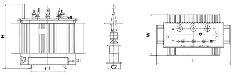
| Rated capacity (kVA) | Dimensions and Mounting Dimensions (mm) | ||||
| L | W | H | C1 | C2 | |
| 30 | 750 | 643 | 974 | 400 | 400 |
| 50 | 795 | 493 | 1013 | 400 | 400 |
| 63 | 800 | 665 | 1050 | 400 | 400 |
| 80 | 840 | 680 | 1075 | 400 | 400 |
| 100 | 775 | 690 | 1100 | 550 | 550 |
| 125 | 1260 | 900 | 1045 | 550 | 550 |
| 160 | 1090 | 720 | 1140 | 550 | 550 |
| 200 | 1180 | 780 | 1155 | 550 | 550 |
| 250 | 1175 | 750 | 1180 | 550 | 550 |
| 315 | 1315 | 890 | 1240 | 660 | 660 |
| 400 | 1330 | 910 | 1280 | 660 | 660 |
| 500 | 1390 | 930 | 1340 | 660 | 660 |
| 630 | 1545 | 1030 | 1410 | 820 | 820 |
| 800 | 1570 | 1020 | 1535 | 820 | 820 |
| 1000 | 1800 | 1250 | 1430 | 820 | 820 |
| 1250 | 1910 | 1130 | 1650 | 820 | 820 |
| 1600 | 2010 | 1220 | 1740 | 820 | 820 |
| 2000 | 2120 | 12807 | 1780 | 820 | 820 |
Documentation Resource Library
FAQ for power distribution transformer
Q: What core advantages does the Fully Sealed Oil-Immersed Power Distribution Transformer have over ordinary power distribution transformer, and how does its sealed design boost performance?
A:
The Fully Sealed Oil-Immersed Power Distribution Transformer is a high-reliability power distribution transformer variant, with its key edge being the fully sealed structure. Unlike conventional power distribution transformer with open or semi-sealed tanks, it isolates transformer oil from air, moisture, and dust, preserving oil insulation performance, avoiding oxidation, and extending the power distribution transformer’s service life.
It eliminates regular oil replacement and breather maintenance, cutting long-term costs. The oil-immersed design ensures efficient heat dissipation for full-load stable operation, and the sealed structure enhances resistance to harsh environments—making this power distribution transformer ideal for outdoor, industrial, and high-humidity scenarios where ordinary models may fail.
Related Products
-
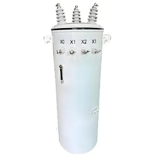
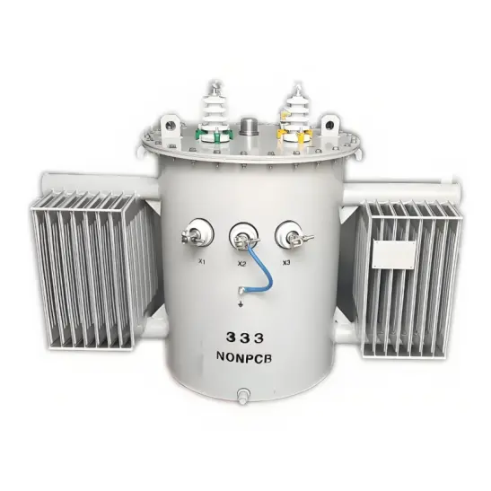
333kVA Single-Phase Pole-Mounted Distribution Transformer
-
Durable H61 H59 Distribution Transformer for Sale-5.5 kV 13.2kV 15kV 33kV
-
High Voltage H61 H59 Distribution Transformer-6kV 6.6kV 7.2kV 10kV
-
HT/BT transformateurs de distribution
-
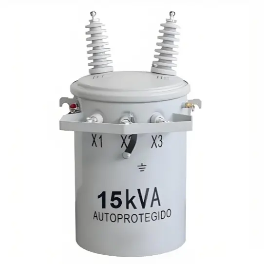
15kVA Single-Phase Pole Mounted Distribution Transformer
-
Oil-immersed distribution transformers Manufacturer-30kV 33kV 35kV 36.5kV 38kV
-
Customization 11kV 20kV 24kV 33kV Three Phase Oil Immersed Distribution Transformer
-
6.3kV 10.5kV 11kV Oil-Immersed Amorphous Alloy Power distribution Transformer
-
6kV 7.2kV 12kV Low-loss Oil-immersed Power distribution transformer
-
Three Phase Power Pole Mounted Oil Immersed Distribution Transformer 11kV