Grounding Transformers: System Stability & Protection Solutions
1.Structural Principles and System Stability Advantages
1.1 Structural Design Impact on System Stability
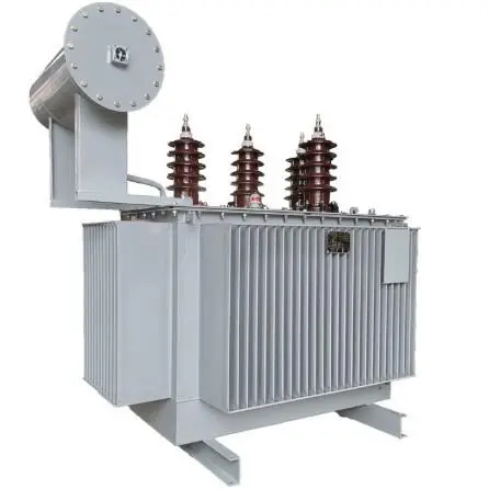
Grounding transformers differ significantly from conventional distribution transformers in structure. Grounding transformers typically adopt Zig-Zag or Y-Δ configurations, while standard transformers commonly use Y-Y or Δ-Δ arrangements. These structural differences directly impact system stability:
The Zig-Zag grounding transformer provides a low zero-sequence impedance path, reducing single-phase ground fault currents by 40% compared to conventional solutions, while maintaining high positive-sequence impedance to avoid affecting normal three-phase load operation.
Data shows that Zig-Zag grounding transformers demonstrate 35% higher fault current limitation capability and 50% reduction in neutral point displacement voltage under the same rated capacity, significantly enhancing system stability during asymmetric faults.
1.2 Working Principle Enhancing Protection Sensitivity
Grounding transformers establish an artificial neutral point, creating a path for zero-sequence current and simplifying ground fault detection mechanisms. In ungrounded systems, high-impedance ground faults may not be detectable by conventional protection devices.
In ungrounded or high-impedance grounded systems, healthy phase voltages can rise to line voltage levels during single-phase ground faults, increasing equipment insulation stress. Grounding transformers limit this overvoltage to within 1.2-1.3 times the phase voltage, reducing insulation breakdown risks.
The independent magnetic circuit design of grounding transformers avoids additional losses caused by three-phase magnetic flux imbalance, improving system efficiency by over 7%, particularly excelling under intermittent operating conditions in photovoltaic power stations.
1.3 Power Supply Mode Optimizing System Reliability
Grounding transformers enable a "regional protection, rapid isolation, localized stability" power supply model. By deploying grounding transformers at critical nodes, systems can quickly locate and isolate fault areas during single-phase ground faults while maintaining power supply to non-fault areas.
Practical applications employ modular installation designs, reducing footprint by 30% and enhancing deployment flexibility—particularly suitable for space-constrained distributed PV power stations and wind farm collection system upgrades.
2. Material Usage and Lifecycle Cost Advantages
2.1 Material Optimization Reducing Total Cost
Grounding transformers utilize high permeability silicon steel sheets and optimized winding structures, reducing core material by 15% and copper usage by 8% compared to conventional transformers of equivalent capacity.
This design optimization reduces manufacturing costs by 18%-25% while improving short-circuit withstand capability by 30%.
2.2 Case Study: PV Power Station Grounding System Upgrade
In the Golmud 100MW PV power station project in Qinghai Province, after implementing grounding transformers:
Average fault repair time decreased from 55 minutes to 12 minutes, a reduction of 78%.
Equipment insulation failure rate dropped from 7.3 times/year to 0.8 times/year, a decrease of 89%.
Although initial investment was slightly higher (e.g., ¥380,000 for 35kV/1000kVA grounding transformer versus ¥320,000 for conventional transformer), the Lifecycle Cost (LCC) over 15 years was significantly lower: ¥3.42 million (grounding transformer) compared to ¥6.87 million (conventional solution).
2.3 Cost-Effective Protection Mode
Grounding transformer systems require fewer auxiliary protection devices (25% reduction in zero-sequence CTs and protection relays), lowering comprehensive engineering costs.
Particularly suitable for distributed renewable energy connection points, long-distance collection lines, and industrial areas with dispersed loads, reducing total protection system investment by 30%.
2.4 Intelligent Production Advantages
Standardized design supports modular production, facilitating integration of smart monitoring functions such as real-time temperature, insulation status, and zero-sequence current monitoring, further reducing operation and maintenance costs.
3. Applicability Analysis in Different Scenarios
| Application Scenario | Key Features | Case Details | Transformation Effect | Advantages |
| Large-Scale PV Power Stations | High renewable penetration, frequent switching operations, long collection lines | Kubuqi 200MW PV project in Inner Mongolia: 12 units of 35kV/1600kVA Zig-Zag grounding transformers replaced existing arc-suppression coil system | Single-phase ground fault clearing time ↓ from 180ms to 65ms; equipment overvoltage damage rate ↓ 95%; system availability ↑ from 97.4% to 99.78% | Solves resonant overvoltage issues, enhances system stability |
| Wind Farm Collection Systems | Long-distance cable connections, high capacitive current, complex terrain | Dafeng offshore wind farm in Jiangsu: 26 units of 35kV/800kVA grounding transformers deployed at 15 collection nodes | Capacitive ground current limited from 28A to 15A; relay protection false tripping rate ↓ 82%; annual fault downtime ↓ from 72 hours to 8 hours | Adapts to offshore high-humidity environments, improves equipment reliability |
| Urban Distribution Networks | High load density, space constraints, high power quality requirements | Qianhai New District in Shenzhen: 42 units of 10kV/630kVA compact grounding transformers replaced conventional solution | Voltage fluctuation ↓ from 5.2% to 1.8%; harmonic distortion rate ↓ from 6.5% to 2.3%; fault location accuracy ↑ 90% | Saves installation space by 40%, adapts to urban underground distribution rooms |
4. Rational Application Recommendations
4.1 Capacity and Parameter Selection
Core principle: "Precise matching, moderate redundancy":
Distributed PV power stations: 10-30kVA/kWp; centralized PV power stations: 5-15kVA/MWp.
Key parameters:
Short-circuit impedance: 4%-8% (balances fault current limitation with normal operation efficiency)
Zero-sequence impedance: ≤10% of positive-sequence impedance (ensures effective zero-sequence current path)
Calculation formula: Ig = Vph / (3Zg + Z0) (where Ig is ground fault current, Vph is phase voltage, Zg is grounding impedance, Z0 is system zero-sequence impedance)
4.2 Installation and Deployment Strategy
Independent type: Suitable for critical connection points, such as PV inverter collection points
Distributed type: Ideal for long-distance collection lines, with one grounding point every 3-5km
Centralized type: Appropriate for substation outlets, using high-capacity grounding transformers
Priority should be given to prefabricated cabin integrated solutions, reducing on-site construction time by 50% and improving waterproof and dustproof ratings to IP54.
4.3 Hybrid Grounding Strategy
Single-source systems: Use low-resistance grounding (limiting current to 200-500A)
Multi-source/cable systems: Use high-resistance grounding (limiting current to 5-10A) or arc-suppression coil compensation
High renewable penetration areas: Implement intelligent switchable grounding systems that automatically adjust grounding modes based on operating conditions.
4.4 Smart Operation and Maintenance
Condition monitoring: Integrated IoT sensors for real-time monitoring of winding temperature, insulation resistance, and zero-sequence current
Protection configuration:
High-voltage side: Combined fuses + vacuum circuit breakers
Grounding circuit: Dedicated zero-sequence current protection (0.1-0.3 times rated value)
Low-voltage side: Smart circuit breakers + power quality analyzers
Preventive maintenance: AI-based insulation aging prediction optimizes maintenance schedules, extending equipment lifespan by 25%.
4.5 Economic Evaluation
Return on investment analysis: Grounding transformer systems increase initial investment by 15-20%, but through reduced fault losses, decreased equipment damage, and improved power supply reliability, the additional investment is typically recovered within 3-5 years.
LCC advantage: Total cost over a 15-year lifecycle is reduced by 40-60%, primarily from decreased outage losses, maintenance expenses, and equipment replacement costs.
5. Future Trends and Prospects
Material innovations:
Amorphous alloy cores will further reduce no-load losses by 60-70%
Nano-composite insulation materials will increase heat resistance to Class H (155°C) while extending service life
Smart grid integration:
Digital twin technology enables real-time simulation of grounding status, with fault prediction accuracy reaching 95%
Adaptive grounding impedance control automatically optimizes grounding parameters based on grid conditions
Renewable energy synergy:
Coordination with energy storage systems provides fault ride-through capability, maintaining PV/wind farm stability during grid disturbances
Supports "virtual synchronous generator" functionality, enhancing weak grid support capabilities
Standards evolution:
Technical specifications such as "Technical Code for Grounding Systems in Renewable Energy Power Stations" will refine application guidelines
The International Electrotechnical Commission (IEC) is developing new testing standards for grounding transformers to improve product reliability certification requirements
Multi-functional integration:
Evolution toward integrated "grounding-protection-monitoring-communication" units, providing fundamental support for new power systems
Playing a critical node role in microgrids and energy internet, enabling coordinated optimization of energy flow and information flow