Grounding Transformer Solutions for Power System Stability and Protection
1. The Essential Role of Grounding Transformers in Modern Power Systems
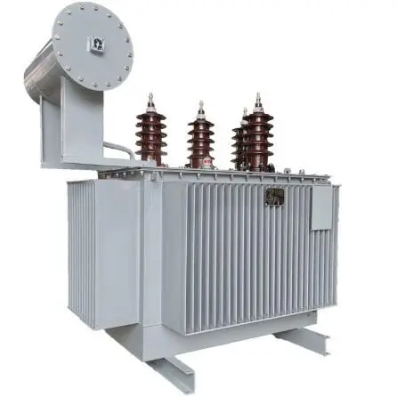
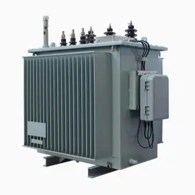
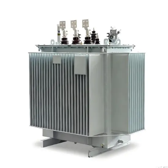
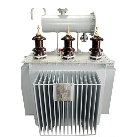
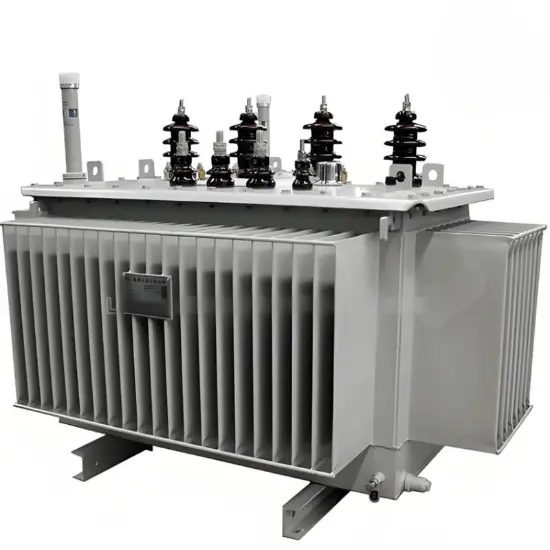
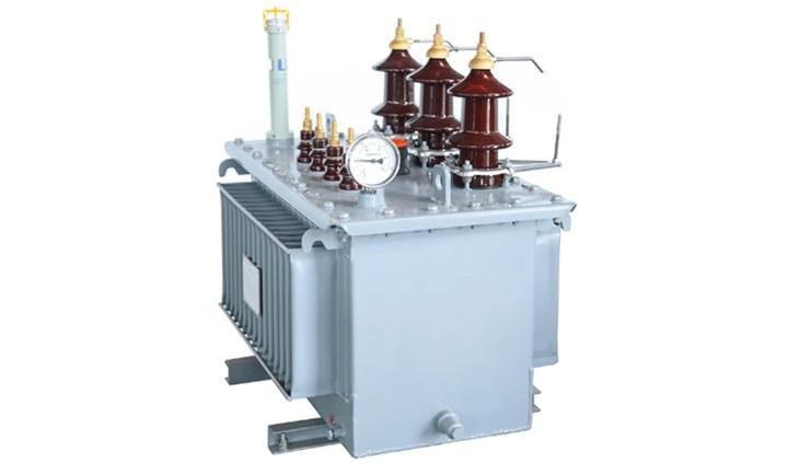
A Grounding Transformer (GT) is a specialized transformer designed to provide a neutral point for grounding in three-phase delta-connected or ungrounded systems. It plays a critical role in renewable energy integration and grid stability. Its primary functions include:
- Neutral Point Creation: Provides an artificial neutral point for effective system grounding in delta-connected networks or systems without inherent neutral points.
- Fault Current Limitation: Controls ground fault currents to safe levels (typically 100-600A), preventing equipment damage while allowing protective devices to operate.
- System Stability Enhancement: Minimizes transient overvoltages during single-line-to-ground faults, protecting sensitive equipment such as inverters in PV systems and extending equipment lifespan.
2. Grounding Transformer Key Technical Parameters and Selection Guidelines
2.1 Capacity and Impedance Selection
Rating Calculation: Must be sized based on fault current requirements and duration (typically 10 seconds to continuous rating). The kVA rating is calculated as: Vline × Ifault × 1.732.
Example: A 35kV distribution network with 200A fault current requirement utilizes a 12.5MVA grounding transformer with zigzag connection.
Zero-Sequence Impedance: Should be carefully selected to limit fault current while maintaining sufficient sensitivity for protection devices (typically 3-10% of positive sequence impedance).
2.2 Core Selection Parameters
| Parameter | Requirement |
| Connection Type | Zigzag (ZN) or Wye-Delta (YNd) configuration preferred |
| Thermal Rating | Minimum 10-second withstand rating of 3× continuous rating |
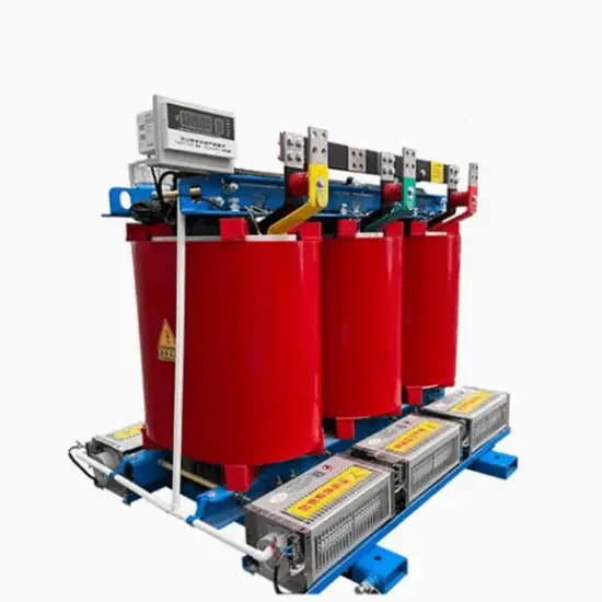
| Protection Class | IP23 minimum for indoor, IP54 for outdoor installations |
| Fault Duration | 10s, 30s, 2hr, or continuous rating based on system requirements |
| Insulation Level | BIL rating matching system voltage class (e.g., 150kV for 35kV systems) |
2.3 System Compatibility Design
- Protection Coordination: Must integrate with system protection schemes, including ground fault relays (50N/51N), neutral overvoltage protection (59N), and breaker interlocking systems.
- Harmonic Performance: Low zero-sequence impedance design to prevent harmonic amplification, especially in systems with power electronic converters.
3. Grounding Transformer System Integration Solutions
Advanced Monitoring and Control Integration
Smart Monitoring System:
- Sensor Configuration: Fiber optic temperature sensors for hotspot detection, neutral current monitoring, and partial discharge sensors for insulation health assessment
- Communication Interface: IEC 61850-9-2 LE support for direct integration with substation automation systems (SAS) and grid management platforms
Protection Enhancements:
- Adaptive Grounding: Dynamic resistance switching capability responding to system conditions
- Remote Management: Cloud-based monitoring platform providing real-time fault recording and predictive maintenance alerts
4. Grounding Transformer Typical Application Case Studies
4.1 220kV Substation Grounding System Upgrade
GT Configuration: Two parallel 16MVA zigzag grounding transformers with 400A neutral resistance, installed at a major metropolitan substation.
Results: Reduced transient overvoltages by 68%, eliminated repeated insulation failures in cable systems, and improved fault clearing time by 42%.
4.2 Offshore Wind Farm Collector System
Solution Features:
- Five 8MVA grounding transformers with marine-grade corrosion protection (ISO 12944 C5-M)
- Sub-cycle fault detection system with <15ms response time
- Integration with turbine SCADA for coordinated fault management
Operational Benefits: Achieved 99.97% availability over three years despite harsh marine environment, with zero unplanned outages related to grounding issues.
4.3 High-Altitude Solar Farm Grounding Solution
Environmental Adaptations:
- High Altitude Design: Special insulation system rated for 4,500m elevation with derating factor of 0.82
- Extreme Temperature Operation: -40°C to +55°C operational range with thermostatically controlled heating elements
- Sand and Dust Protection: Enhanced air filtration system with automatic backflushing capability
5. Economic Benefits and Maintenance Optimization
5.1 Investment Return Analysis
Industrial Park 10kV Network: Implementation of grounding transformers with 250A neutral resistance reduced equipment damage costs by 187,000annually,withROIachievedin2.7yearsdespiteinitialcapitalinvestmentof340,000.
5.2 Advanced Maintenance Strategy
Predictive Diagnostics:
- Dielectric Response Analysis: FDS (Frequency Domain Spectroscopy) testing to detect moisture ingress before failure
- Dynamic Loading Assessment: Real-time thermal modeling predicting remaining life under varying load profiles
Remote Condition Monitoring:
- AI-powered anomaly detection system analyzing 15+ operational parameters
- Automated maintenance scheduling triggered by actual equipment condition rather than fixed time intervals
- Reduced maintenance costs by 35% while extending equipment life by approximately 8 years through optimized operation
Note: All grounding transformer solutions are engineered to comply with IEEE C57.116, IEC 60076-14, and local grid code requirements for fault contribution and protection coordination.