Grounding Transformer Solutions for Modern Power Grids
1. Core Challenges in Modern Power Systems
1.1 Diverse Grounding Standards
Global grounding requirements vary significantly: Unearthed/High-resistance grounded systems dominate in mining and critical industrial applications; Peterson coil grounding is common in European distribution networks; while low-resistance grounding prevails in North American utilities. Modern renewable integration adds complexity with varying grounding requirements at different voltage levels (11kV, 33kV, 66kV).
1.2 Renewable Integration Challenges
Inverter-based resources (solar, wind) lack inherent fault current contribution, creating protection coordination difficulties. High penetration of power electronics increases sensitivity to transient overvoltages during single-line-to-ground faults. Grid codes increasingly require precise fault current control (typically 200A-1000A) with fast clearing times (<100ms).
1.3 Reliability and Safety Requirements
Utilities demand 99.99% availability for grounding systems despite harsh conditions. Safety standards require effective ground fault current limitation to prevent step/touch potential hazards. Aging infrastructure necessitates retrofit solutions compatible with existing protection schemes while minimizing downtime during installation.
2. Technical Solutions for Grounding Transformers
2.1 Customized Grounding Configuration Design
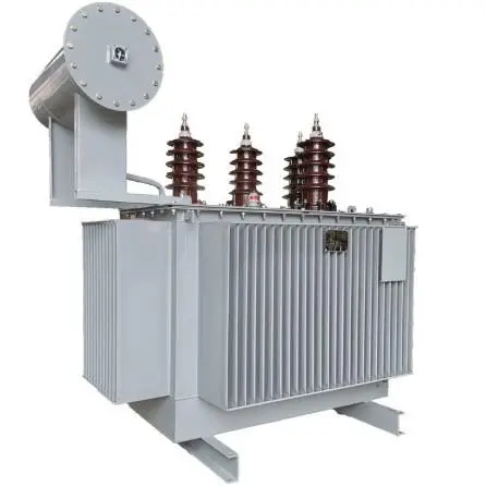
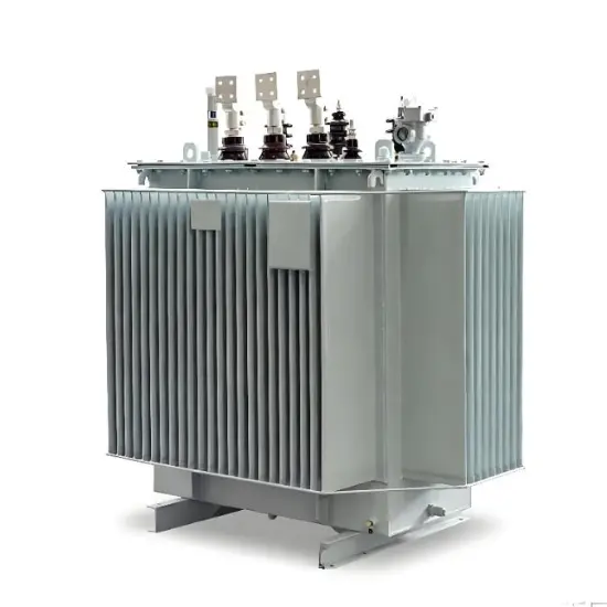
Connection Flexibility: Offers Zigzag (ZNyn), Wye-Broken Delta (YNd), and Wye-Delta (YNd11) configurations adaptable to different system requirements. Zigzag configuration provides lowest zero-sequence impedance (1.1-1.8 p.u.) with no phase shift.
Impedance Engineering: Precision calculation of zero-sequence impedance to balance fault current limitation (200-600A typical) with sufficient sensitivity for protective relays. Short-time rating designed for 10s, 30s, 2hr, or continuous duty based on system analysis.
2.2 Material and Structural Enhancement
| Component | Technical Solution | Benefit |
| Core | Laser-cut grain-oriented silicon steel with stepped-lap joints | ↓15% core losses, ↓30% noise level compared to conventional designs |
| Windings | Continuously transposed conductor (CTC) with epoxy impregnation | Enhanced short-circuit withstand capability (25kA/2s), reduced hotspots |
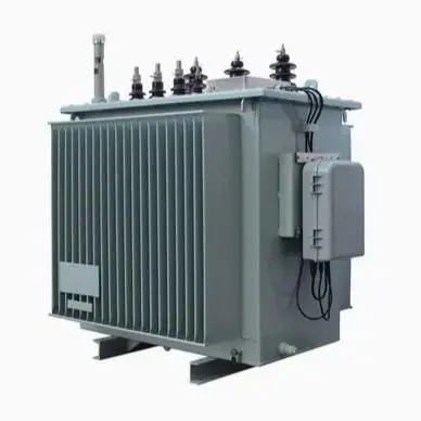
| Enclosure | Galvanized steel with powder coating + optional stainless steel (marine environments) | Salt spray resistance >1500hrs (IEC 60068-2-52 compliant) |
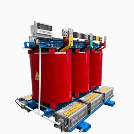
2.3 Intelligent Protection & Monitoring
Integrated Protection System: Dual neutral current sensing (CT + Rogowski coil) with redundant outputs to protection relays. Built-in neutral displacement voltage monitoring with automatic alarm thresholds.
Smart Monitoring Platform: Fiber optic temperature sensors at critical hotspots; partial discharge monitoring for early insulation degradation detection. Cloud-based analytics platform predicts remaining life and maintenance needs, reducing unplanned outages by 40%.
3. Environmental Adaptability Design
3.1 Thermal Management Optimization
Forced Cooling System: Thermostatically controlled fans with variable speed drives, enabling 40% overload capacity for 2 hours during peak demand. Thermal modeling ensures hotspot temperature never exceeds 110°C even at 50°C ambient temperature.
High-Altitude Derating: Special design considerations for installations above 1000m altitude with automatic derating compensation algorithms. For 3000m installations, optimized insulation system maintains BIL rating without excessive clearance requirements.
3.2 Extreme Environment Protection
Passes IEEE 693 seismic testing (Zone 4 requirements) with proven performance in earthquake-prone regions. IP55 enclosure rating protects against dust and water jets (IEC 60529 compliant), suitable for outdoor installation without additional shelter. Optional winterization package for -40°C operation with thermostatically controlled heaters and cold-flow oil.
4. Application Scenarios & Selection Guidelines
4.1 Grounding Transformer Types & Recommended Applications
| Type | Rating Range | Key Features | Recommended Applications |
| Zigzag Grounding Transformer | 500kVA ~ 10MVA | Lowest impedance, no phase shift, inherent harmonic rejection | Solar farms, data centers, critical industrial facilities |
| Wye-Delta Grounding Transformer | 1MVA ~ 25MVA | Higher impedance control, phase shift capability, can provide auxiliary power | Utility substations, wind farms, industrial complexes |
| Resonant Grounding System | 2MVA ~ 40MVA | Petersen coil integration, adaptive tuning, arc suppression | Mining operations, railway networks, urban distribution |
4.2 Critical Technical Parameters
Electrical Parameters
- Short-time Rating: 10s, 30s, 2hr or continuous (per IEEE C57.116)
- Zero-sequence impedance tolerance: ±7.5% (critical for protection coordination)
- Neutral-to-ground voltage withstand: 1.3× maximum expected during faults
Protection & Control
- Built-in neutral grounding resistor (NGR) with temperature monitoring
- Optional auxiliary windings for station service power (400V/480V)
- Multiple CT options (protective class 5P20, metering class 0.5)
4.3 System Integration & Harmonic Management
Protection Coordination:
- Configurable time-current curves compatible with modern digital relays (SEL, GE, Siemens)
- Sub-cycle fault detection (<20ms) with optional high-speed contactor interface
Harmonic Mitigation:
- Zero-sequence harmonic filtering capability (3rd, 9th, 15th)
- Special harmonic-resistant design for systems with >15% THD content
- Active filtering interface option for critical applications
5. Service & Support Ecosystem
- Global Manufacturing Network: Production facilities in North America, Europe, and Asia with standardized quality control processes. 85% of standard products available from regional warehouses with 4-week delivery guarantee.
- Predictive Maintenance Program: AI-powered health assessment using transformer's operational data history. Remote diagnostics capabilities resolve 80% of issues without site visits. Condition-based maintenance scheduling extends equipment life by 25% compared to time-based approaches.
- Standards Compliance: Certified to IEEE C57.116, IEC 60076-14, ANSI C57.12.00, and local grid code requirements. Special certifications available for mining (MSHA), petrochemical (ATEX), and maritime applications. Full test reports including short-circuit withstand verification and temperature rise tests provided with each unit.