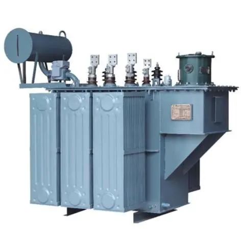
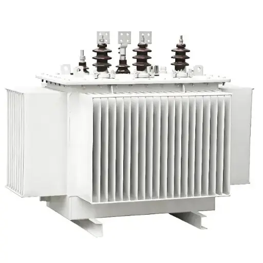
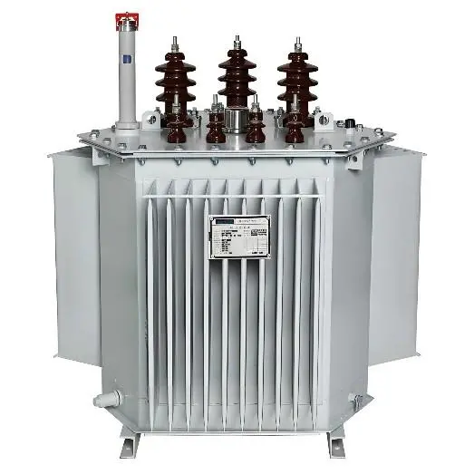
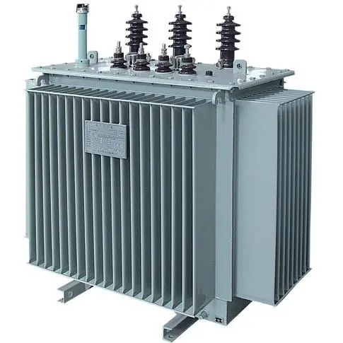
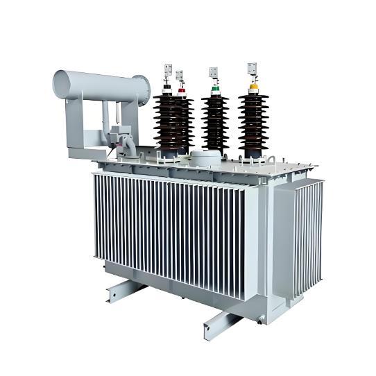
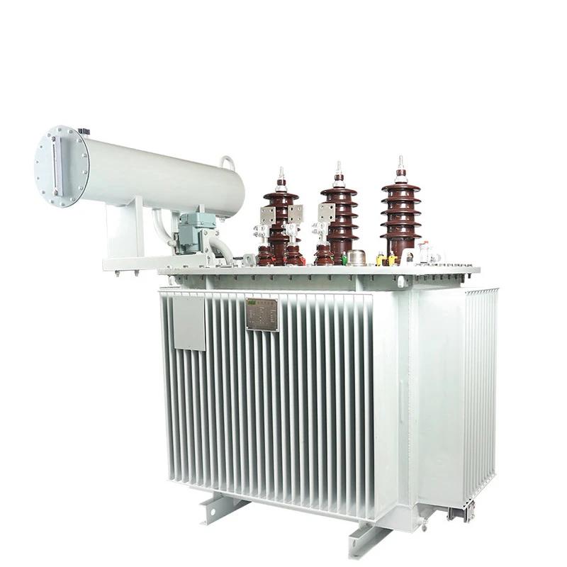
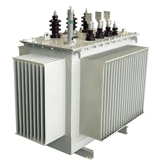
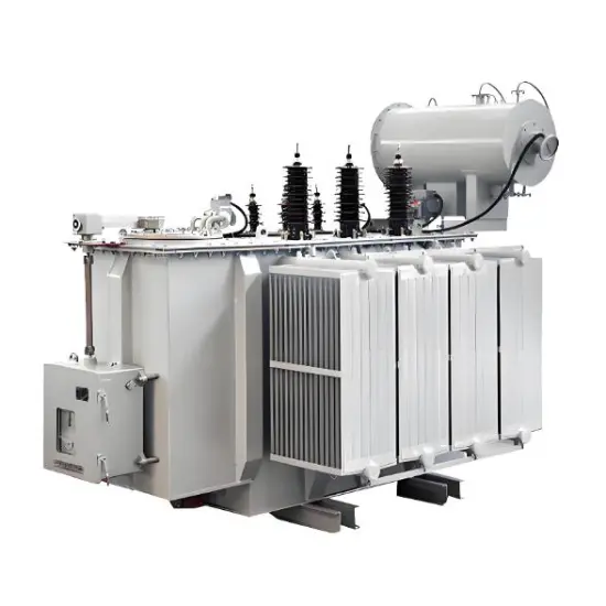
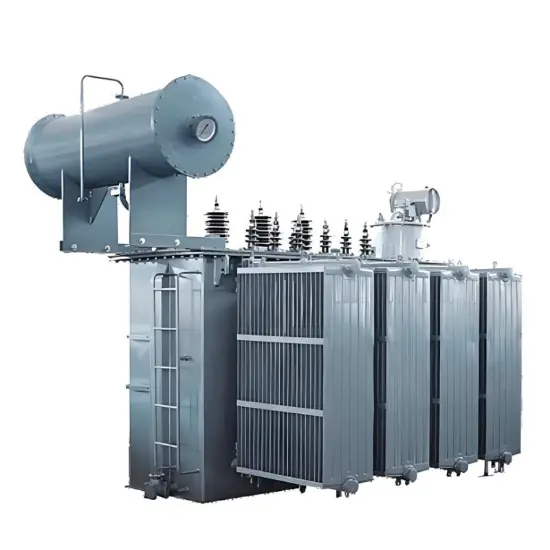
Oil Immersed Fully Sealed Distribution Transformer 10kV 10.5kV 11kV
| Brand | Vziman |
| Model NO. | Oil Immersed Fully Sealed Distribution Transformer 10kV 10.5kV 11kV |
| Rated capacity | 200kVA |
| Series | S11 |
Oil-Immersed Distribution Transformers Product Overview
Oil-Immersed Distribution Transformers Model Designation and Its Meanin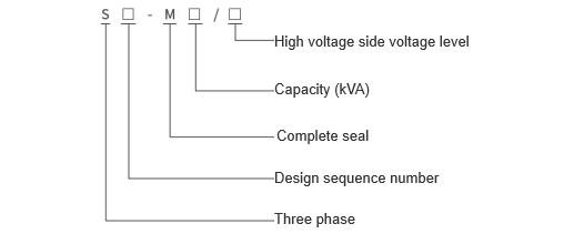
Oil-Immersed Distribution Transformers Product Features
Core:The core of the Oil-Immersed Fully Sealed Distribution Transformer is made from high-permeability, grain-oriented cold-rolled silicon steel sheets. It features a new design with fully slanted joints and stacked construction, where the core column has a multi-step circular cross-section and the yoke matches the core's cross-sectional area. This structural design effectively enhances the product's operational stability.
Windings:The windings of the Oil-Immersed Fully Sealed Distribution Transformer utilize corrugated oil channels and do not require impregnation. They are tightly bound using binding straps. All windings are concentric coils: the high-voltage winding includes taps corresponding to different voltage requirements, which connect to the tap changer mounted on the tank cover. Voltage adjustments can only be made after power disconnection.
Safety Protection Devices:Oil-Immersed Fully Sealed Distribution Transformers ranging from 30kVA to 2000kVA are equipped with pressure relief valves. Gas relays with alarm and trip contacts can be installed based on user requirements.
Oil Temperature Measurement Device:All Oil-Immersed Fully Sealed Distribution Transformers feature a glass thermometer holder located at the top of the oil tank, extending into the oil by 120±10mm. For models between 1000kVA and 2000kVA, outdoor signal thermometers are installed.
Transformer Tank:The transformer tank of the Oil-Immersed Fully Sealed Distribution Transformer is constructed with corrugated walls. The surface is treated with anti-corrosion coating, ensuring a strong paint film. The corrugated cooling fins not only provide cooling but also have an "expansion" function, compensating for changes in transformer oil volume due to temperature fluctuations. Thus, this type of transformer does not require an oil conservator, reducing the overall height. During encapsulation, vacuum oil filling is adopted to completely remove moisture, preventing the transformer oil from coming into contact with air. This effectively avoids oxygen and moisture intrusion that could degrade insulation performance and accelerate oil aging, thus eliminating the need for periodic oil sample tests.
S11-M Series 10kV Oil-Immersed Fully Sealed Distribution Transformer Technical Specifications
| Capacity (kVA) | Rated Voltage (kV) | Connection Group Designation | Losses (kW) | Short-Circuit Impedance (%) | No-Load Current (%) | Weight (kg) | External Dimensions (mm) | Shaft Center Distance (mm) | |||||
| High Voltage | High Voltage Tap | Low Voltage | No-Load | Load | Oil Tank Weight | Equipment Total Weight | Total Weight | ||||||
| 30 | 6 6.3 10 10.5 11 |
±5% ±2×2.5% |
0.4 | Yyn0 Dyn11 |
0.10 | 0.63/0.60 | 4.0 | 1.5 | 95 | 150 | 370 | 1070×660×960 | 400×400 |
| 50 | 0.13 | 0.91/0.87 | 1.3 | 110 | 210 | 460 | 1130×700×1010 | 400×400 | |||||
| 63 | 0.15 | 1.09/1.04 | 1.2 | 115 | 240 | 505 | 1150×710×1070 | 550×550 | |||||
| 80 | 0.18 | 1.31/1.25 | 1.2 | 135 | 300 | 600 | 1190×720×1130 | 550×550 | |||||
| 100 | 0.20 | 1.58/1.50 | 1.1 | 135 | 330 | 610 | 1210×800×1140 | 550×550 | |||||
| 125 | 0.24 | 1.89/1.80 | 1.1 | 153 | 388 | 720 | 1320×820×1160 | 550×550 | |||||
| 160 | 0.28 | 2.31/2.20 | 1 | 164 | 448 | 800 | 1350×835×1190 | 550×550 | |||||
| 200 | 0.34 | 2.73/2.60 | 1 | 182 | 540 | 910 | 1360×845×1225 | 550×550 | |||||
| 250 | 0.40 | 3.2/3.05 | 0.9 | 217 | 655 | 1090 | 1380×875×1275 | 660×660 | |||||
| 315 | 0.48 | 3.83/3.65 | 0.9 | 300 | 810 | 1390 | 1430×880×1390 | 660×660 | |||||
| 400 | 0.57 | 4.52/4.30 | 0.8 | 330 | 940 | 1610 | 1500×880×1430 | 660×660 | |||||
| 500 | 0.68 | 5.41/5.15 | 0.8 | 390 | 1190 | 1970 | 1590×900×1530 | 660×660 | |||||
| 630 | 0.81 | 6.20 | 4.5 | 0.6 | 420 | 1360 | 2210 | 1670×930×1550 | 660×660 | ||||
| 800 | 0.98 | 7.50 | 0.6 | 600 | 1570 | 2750 | 1750×1030×1640 | 660×660 | |||||
| 1000 | 1.15 | 10.3 | 0.6 | 671 | 1672 | 3200 | 1790×1100×1730 | 820×820 | |||||
| 1250 | 1.36 | 12.8 | 0.5 | 757 | 1964 | 3710 | 1930×1210×1750 | 820×820 | |||||
| 1600 | 1.64 | 14.5 | 0.5 | 859 | 2382 | 4370 | 2000×1230×1860 | 820×820 | |||||
| 2000 | 1.94 | 18.3 | 0.4 | 1000 | 2795 | 5130 | 2050×1340×2080 | 820×820 | |||||
| 2500 | 2.29 | 21.2 | 0.4 | 1200 | 3200 | 5850 | 2100×1390×2250 | 820×820 | |||||
Notes:
- Distribution transformers with various special parameters and performance characteristics can be manufactured according to customer requirements.
- The load loss values above the slash in the table apply to the Dyn11 connection group, while those below the slash apply to the Yyn0 connection group.
- External dimensions and weights may vary based on customer and market requirements; therefore, the actual data provided in the factory documentation shall prevail.
S11 Type 10kV Oil-Immersed Fully Sealed Distribution Transformer Technical Specifications:
| Capacity (kVA) | Rated Voltage (kV) | Connection Group Designation | Losses (kW) | Short-Circuit Impedance (%) | No-Load Current (%) | Weight (kg) | External Dimensions (mm) | Shaft Center Distance (mm) | |||||
| High Voltage | High Voltage Tap | Low Voltage | No-Load | Load | Oil Tank Weight | Equipment Total Weight | Total Weight | ||||||
| 200 | 6 6.3 10 10.5 |
±4×2.5% | 0.4 | Yyn0 Dyn11 |
0.38 | 2.90 | 4.0 | 1.0 | 280 | 605 | 1280 | 1700×980×1550 | 550×550 |
| 250 | 0.44 | 3.42 | 0.90 | 320 | 670 | 1330 | 1780×995×1590 | 550×550 | |||||
| 315 | 0.53 | 4.10 | 0.90 | 435 | 845 | 1715 | 1935×1220×1725 | 660×660 | |||||
| 400 | 0.64 | 4.95 | 0.80 | 480 | 1010 | 1980 | 2025×1350×1850 | 660×660 | |||||
| 500 | 0.76 | 5.89 | 0.80 | 530 | 1300 | 2350 | 2080×1410×1920 | 660×660 | |||||
| 630 | 0.96 | 7.26 | 4.5 |
0.60 | 715 | 1525 | 2950 | 2110×1460×1980 | 820×820 | ||||
| 800 | 1.12 | 8.89 | 0.60 | 900 | 1595 | 3405 | 2470×1630×2270 | 820×820 | |||||
| 1000 | 1.36 | 10.4 | 0.60 | 795 | 1730 | 3420 | 2560×1675×2540 | 820×820 | |||||
| 1250 | 1.56 | 12.3 | 0.50 | 980 | 2650 | 4610 | 2605×1720×2770 | 820×820 | |||||
| 1600 | 1.92 | 14.7 | 0.50 | 1210 | 3105 | 5350 | 2610×1850×2810 | 1070×1070 | |||||
| 2000 | 2.27 | 18.6 | 5 |
0.40 | 1780 | 3520 | 6800 | 2780×2475×2815 | 1070×1070 | ||||
| 2500 | 2.68 | 21.6 | 0.40 | 2050 | 3985 | 8040 | 2820×2425×2635 | 1070×1070 | |||||
Note:
- Transformers with various special parameters and performance characteristics can be manufactured according to customer requirements.
- External dimensions and weights may vary based on customer and market needs; therefore, the data for these two items in the table are subject to the official factory documentation.
S11 Type 35kV Oil-Immersed Fully Sealed Distribution Transformer with Off-Circuit Tap Changer Technical Specifications:
| Capacity (kVA) | Rated Voltage (kV) | Connection Group Designation | Losses (kW) | Short-Circuit Impedance (%) | No-Load Current (%) | Weight (kg) | External Dimensions (mm) | Shaft Center Distance (mm) | |||||
| High Voltage | High Voltage Tap | Low Voltage | No-Load | Load | Oil Tank Weight | Equipment Total Weight | Total Weight | ||||||
| 50 | 35 38.5 |
±5% ±2×2.5% |
0.4 | Yyn0 Dyn11 |
0.16 | 1.20 | 6.5 | 1.3 | 330 | 300 | 860 | 1195×935×1825 | 660×660 |
| 100 | 0.23 | 2.01 | 1.1 | 385 | 470 | 1130 | 1200×965×1935 | 660×660 | |||||
| 125 | 0.27 | 2.37 | 1.1 | 465 | 550 | 1335 | 1235×940×1955 | 660×660 | |||||
| 160 | 0.28 | 2.82 | 1.0 | 485 | 580 | 1475 | 1285×895×1960 | 660×660 | |||||
| 200 | 0.34 | 3.32 | 1.0 | 595 | 680 | 1755 | 1310×1150×1985 | 660×660 | |||||
| 250 | 0.40 | 3.95 | 0.95 | 650 | 860 | 2000 | 1450×1090×2010 | 660×660 | |||||
| 315 | 0.48 | 4.75 | 0.95 | 765 | 980 | 2290 | 1630×1065×2110 | 820×820 | |||||
| 400 | 0.58 | 5.74 | 0.85 | 885 | 1170 | 2725 | 1850×1155×2015 | 820×820 | |||||
| 500 | 0.68 | 6.91 | 0.85 | 960 | 1340 | 3090 | 2045×1205×2415 | 820×820 | |||||
| 630 | 0.83 | 7.86 | 0.65 | 895 | 1550 | 3810 | 2085×1240×2515 | 820×820 | |||||
| 800 | 0.98 | 9.4 | 0.65 | 1030 | 1990 | 4510 | 2305×1615×2685 | 820×820 | |||||
| 1000 | 1.15 | 11.5 | 0.65 | 1475 | 2415 | 5055 | 2545×1540×2590 | 820×820 | |||||
| 1250 | 1.40 | 13.9 | 0.60 | 1485 | 2480 | 5290 | 2495×2010×2675 | 820×820 | |||||
| 1600 | 1.69 | 16.6 | 0.60 | 1490 | 2600 | 5450 | 2680×2100×2970 | 820×820 | |||||
| 2000 | 1.99 | 19.7 | 0.55 | 1495 | 3275 | 6380 | 2545×2650×2740 | 820×820 | |||||
| 2500 | 2.36 | 23.2 | 0.55 | 1795 | 3575 | 7230 | 2570×2490×2875 | 1070×1070 | |||||
Note:
- Transformers with various special parameters and performance characteristics can be manufactured according to customer requirements.
- External dimensions and weights may vary depending on customer and market demands; therefore, the data for these two items in the table shall be as specified in the official factory documentation.
S13-M Series 10kV Oil-Immersed Fully Sealed Distribution Transformer Technical Specifications:
| Capacity (kVA) | Rated Voltage (kV) | Connection Group Designation | Losses (kW) | Short-Circuit Impedance (%) | No-Load Current (%) | Weight (kg) | External Dimensions (mm) | Shaft Center Distance (mm) | |||||
| High Voltage | High Voltage Tap | Low Voltage | No-Load | Load | Oil Tank Weight | Equipment Total Weight | Total Weight | ||||||
| 30 | 6 6.3 10 10.5 11 |
±5% ±2×2.5% |
0.4 | Yyn0 Dyn11 |
0.08 | 0.63/0.60 | 4.0 | 1.61 | 95 | 150 | 280 | 810x650x820 | 400×400 |
| 50 | 0.1 | 0.91/0.87 | 1.4 | 110 | 210 | 390 | 820x680x840 | 400×400 | |||||
| 63 | 0.11 | 1.09/1.04 | 1.33 | 115 | 240 | 440 | 850x700x860 | 550×550 | |||||
| 80 | 0.13 | 1.31/1.25 | 1.33 | 135 | 300 | 495 | 900x730x930 | 550×550 | |||||
| 100 | 0.15 | 1.58/1.50 | 1.26 | 135 | 330 | 600 | 910x750x990 | 550×550 | |||||
| 125 | 0.17 | 1.89/1.80 | 1.19 | 153 | 388 | 690 | 1000x760x1060 | 550×550 | |||||
| 160 | 0.20 | 2.31/2.20 | 1.12 | 164 | 448 | 780 | 1090x770x1135 | 550×550 | |||||
| 200 | 0.24 | 2.73/2.60 | 1.05 | 182 | 540 | 910 | 1120x790x1165 | 550×550 | |||||
| 250 | 0.29 | 3.2/3.05 | 0.98 | 217 | 655 | 1040 | 1140x810x1220 | 660×660 | |||||
| 315 | 0.34 | 3.83/3.65 | 0.98 | 300 | 810 | 1190 | 1170x830x1240 | 660×660 | |||||
| 400 | 0.41 | 4.52/4.30 | 0.91 | 330 | 940 | 1430 | 1220x1020x1270 | 660×660 | |||||
| 500 | 0.48 | 5.41/5.15 | 0.84 | 390 | 1190 | 1650 | 1300x1180x1320 | 660×660 | |||||
| 630 | 0.57 | 6.20 | 4.5 | 0.77 | 420 | 1360 | 2030 | 1500x1210x1480 | 660×660 | ||||
| 800 | 0.70 | 7.50 | 0.70 | 600 | 1570 | 2320 | 1840x1250x1620 | 660×660 | |||||
| 1000 | 0.83 | 10.3 | 0.70 | 671 | 1672 | 2600 | 1890x1400x1680 | 820×820 | |||||
| 1250 | 0.97 | 12.0 | 0.63 | 757 | 1964 | 2890 | 2050x1460x1710 | 820×820 | |||||
| 1600 | 1.17 | 14.5 | 0.56 | 859 | 2382 | 3380 | 2200x1520x1950 | 820×820 | |||||
Note:
- Distribution transformers with various special parameters and performance characteristics can be manufactured according to customer requirements.
- The load loss values shown above the slash in the table apply to the Dyn11 connection group, while those below the slash apply to the Yyn0 connection group.
- External dimensions and weights may vary based on customer and market requirements; therefore, the data for these two items in the table are subject to the official factory documentation.
- Urban Distribution Network Renovation: The Oil Immersed Distribution Transformer is suitable for 10kV/11kV urban grid nodes. Its fully sealed structure resists high humidity and dust, ensuring long-term stable outdoor operation and reducing O&M costs.
- Industrial Park Power Supply: The Oil Immersed Distribution Transformer is compatible with 10.5kV voltage. It isolates industrial corrosive gases and features a maintenance-free design, meeting the continuous production power demand of industrial parks.
- Rural & Remote Area Power Distribution: The Oil Immersed Distribution Transformer flexibly matches 10kV/11kV voltage grades. Its fully sealed structure eliminates the need for oil refilling, addressing the shortage of O&M resources in remote areas.
- Commercial Building Power Distribution: The Oil Immersed Distribution Transformer boasts a compact, fully sealed structure, suitable for 10kV indoor and outdoor installation, and avoids safety hazards caused by oil leakage.
- New Energy Grid Connection: The Oil Immersed Distribution Transformer adapts to 10.5kV/11kV grid connection voltage. It resists harsh environments and copes with current fluctuations from new energy power generation.
- Municipal Engineering Power Distribution: The Oil Immersed Distribution Transformer supports 10kV temporary and permanent power supply, and its fully sealed performance adapts to the complex environment of construction sites.
- Ambient Temperature:The Oil-Immersed Fully Sealed Distribution Transformer is suitable for use in environments with a temperature range of -25℃ to 40℃. For areas where the temperature is lower than -25℃, low-temperature resistant transformer oil must be used to ensure the fluidity of the oil and the normal operation of the Oil-Immersed Fully Sealed Distribution Transformer.
- Ambient Humidity:The Oil-Immersed Fully Sealed Distribution Transformer can operate in an environment with a relative humidity not exceeding 90% (at 25℃, no condensation). Its fully sealed structure can effectively prevent moisture from entering the interior, so the Oil-Immersed Fully Sealed Distribution Transformer is also adaptable to humid scenarios such as coastal industrial zones and underground substations.
- Environmental Cleanliness:The Oil-Immersed Fully Sealed Distribution Transformer allows moderate dust in the operating environment, but it is strictly prohibited to use it in places with heavy dust accumulation, corrosive gases or flammable and explosive vapors. For dusty working conditions such as metallurgy and mining, simple dust-proof shielding measures should be taken for the Oil-Immersed Fully Sealed Distribution Transformer to avoid dust affecting the insulation performance of internal components.
- Power System Parameters:The Oil-Immersed Fully Sealed Distribution Transformer is applicable to AC 50Hz (or 60Hz customized) power systems, and the system voltage fluctuation should not exceed ±5% of the transformer's rated voltage. It is forbidden to operate the Oil-Immersed Fully Sealed Distribution Transformer beyond the rated capacity for a long time to prevent overheating and damage to the equipment.
- Installation Site Requirements:The Oil-Immersed Fully Sealed Distribution Transformer should be installed in a well-ventilated site without severe vibration and impact. The installation ground should be flat and firm, which can bear the weight of the Oil-Immersed Fully Sealed Distribution Transformer and avoid equipment displacement or deformation during operation.
Related Products
-
Sealed Oil-Immersed power Transformer | 6.3kV to 10.5kV

-
10kV Silicon Steel Core Oil immersed Transformer
-
High-Quality 35kV Oil-Immersed Power Transformer by Vziman
-
Oil-Immersed Sealed Power Transformer-15.6kV 17.5kV 20kV

-
11kV Medium Voltage Conventional Dry-type Power Transformers
-
22kV 2500KVA Medium Voltage Step-Up Dry-Type Power Isolation Transformer
-
20kV Dry-Type Distribution Transformer with Off-Circuit Tap Changer
-
35kV-Class SCB Series medium voltage dry-type power transformers
-
Three Phase Oil Immersed On-Load Tap-Changing Power Transformers 35kV 38.5kV
-
Three-Phase Oil-Immersed off-Circuit Tap Changer Power Transformers 35kV 38.5kV