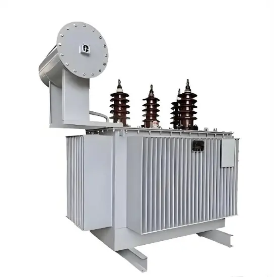
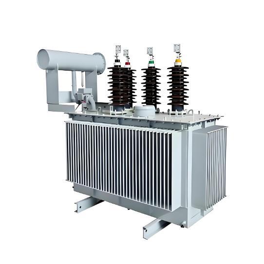
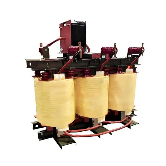
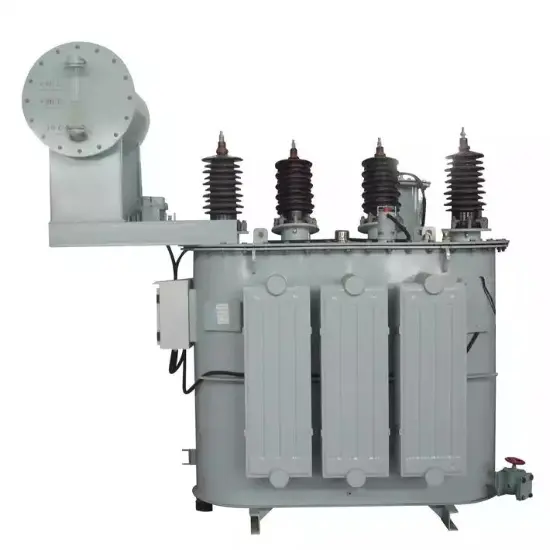
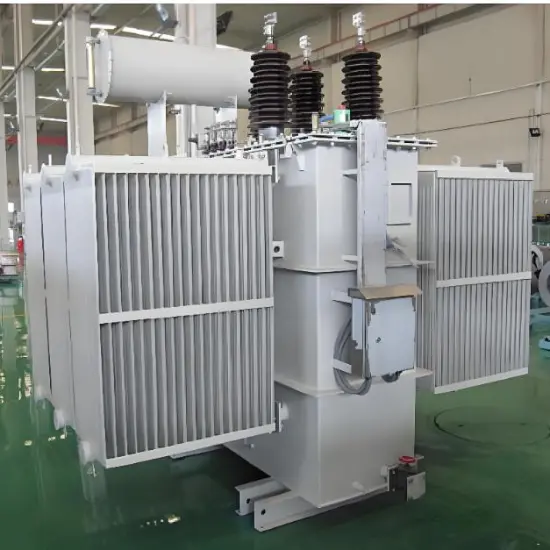
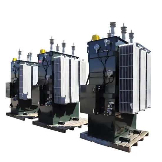
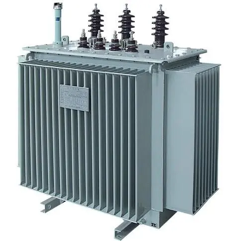
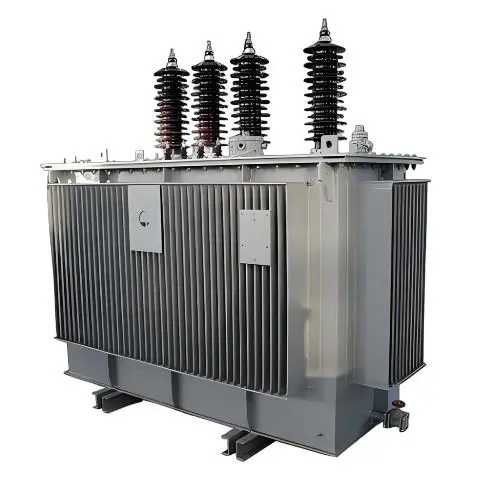
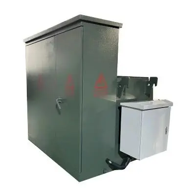
35kV 3 Phase Oil-immersed Grounding transformers
| Brand | Vziman |
| Model NO. | 35kV 3 Phase Oil-immersed Grounding transformers |
| Rated voltage | 35kV |
| Rated frequency | 50/60Hz |
| Rated capacity | 500kVA |
| Series | JDS |
1.Standards: IEC 60076, GB/T 1094, GB/T 25446-2010
2.Power Rating: 30kVA-2500 kVA
3.Primary Voltage: 35kV
4.Secondary Voltage: 0.4 kV or as required
5.Voltage regulation mode: off-circuit tap changing
6.Frequency: 50HZ or 60HZ
7.Type: 3 Phase Electric Power Transformer
8.Connection Type: Dyn11, Yyn0, or per client specification
9.insulation grade:A
10.Cooling method: ONAN
11.Scope of application: The core application scope of oil-immersed grounding transformers is concentrated in medium and low-voltage non-effectively grounded systems. They are mainly used in scenarios such as neutral point extraction, capacitive current compensation, grounding fault handling, and zero-sequence parameter monitoring. They are particularly suitable for distribution networks, small-scale power generation systems, and industrial and civil power networks with high requirements for power supply reliability.
35kV Oil-immersed Grounding transformers Working conditions
1.Ambient Temperature: No more than +40℃ No less than -25℃, The monthly average temperature is no more than +30℃, The yearly average temperature is no more than +20℃
2.Altitude: No more than 1000m.
3.Relative air humidity:≤90%
4.installation site: no corrosion gas, No obvious dirt
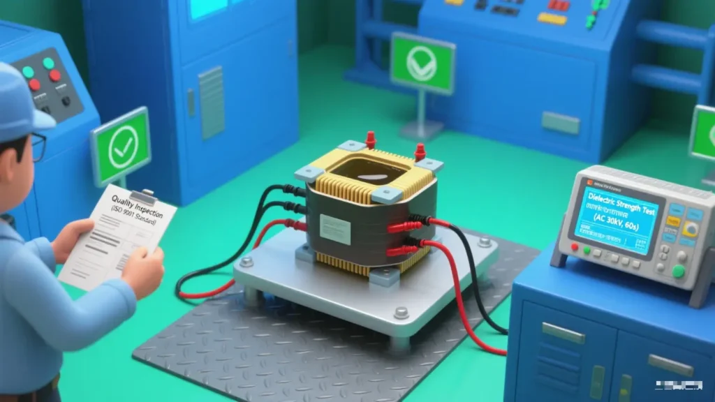
The tests for oil-immersed grounding transformers
The test types for oil-immersed grounding transformers include four categories: factory tests, type tests, on-site tests, and preventive tests:
1.Factory Tests (Mandatory before leaving the factory to ensure the qualification of individual equipment)
Factory tests are conducted on each finished product to verify whether the equipment meets design requirements and factory standards. They mainly include:
①Insulation tests: insulation resistance measurement, dielectric loss factor (tanδ)
②measurement, power frequency withstand voltage test, induced withstand voltage test
③Winding DC resistance measurement
④Transformation ratio test
⑤No-load test
⑥Short-circuit test
⑦Sealing test
2.Type Tests (Conducted during new product finalization or design changes to verify overall performance)
Type tests are a comprehensive verification of the rationality of product design. In addition to all items of factory tests, the following items need to be added:
①Temperature rise test
②Lightning impulse test
③Switching impulse test
④Short-time withstand current test
⑤Zero-sequence impedance measurement
⑥Sound level measurement
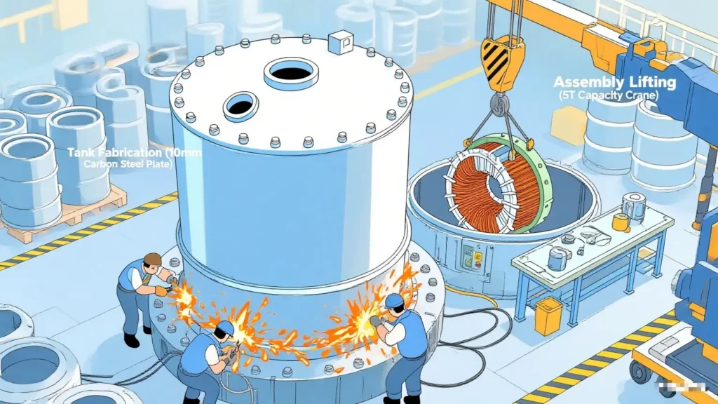
⑦Oil tank mechanical strength test
3.On-site Tests (Conducted before installation and commissioning to verify installation quality and transportation impact)
On-site tests are carried out after the equipment is transported to the site and installed. They focus on checking whether the equipment is damaged during transportation and installation. The main items include:
①Visual inspection
②Insulation resistance and polarization index measurement
③Transformation ratio test and group verification
④DC resistance measurement
⑤Power frequency withstand voltage test (partial)
⑥Oil quality test
4.Preventive Tests (Conducted regularly during operation to ensure long-term safe operation)
Preventive tests are carried out periodically (usually every 1-3 years) to detect potential defects of equipment at an early stage. The main items include:
①Insulating oil test
②Winding insulation resistance and tanδ measurement
③DC resistance measurement
④Retesting of transformation ratio and zero-sequence impedance
⑤Infrared temperature measurement
⑥Core insulation resistance measurement
Component inspection of oil-immersed transformers
1.Winding Inspection:
①DC Resistance Measurement
②Insulation Resistance Test
③Dielectric Loss Factor Test
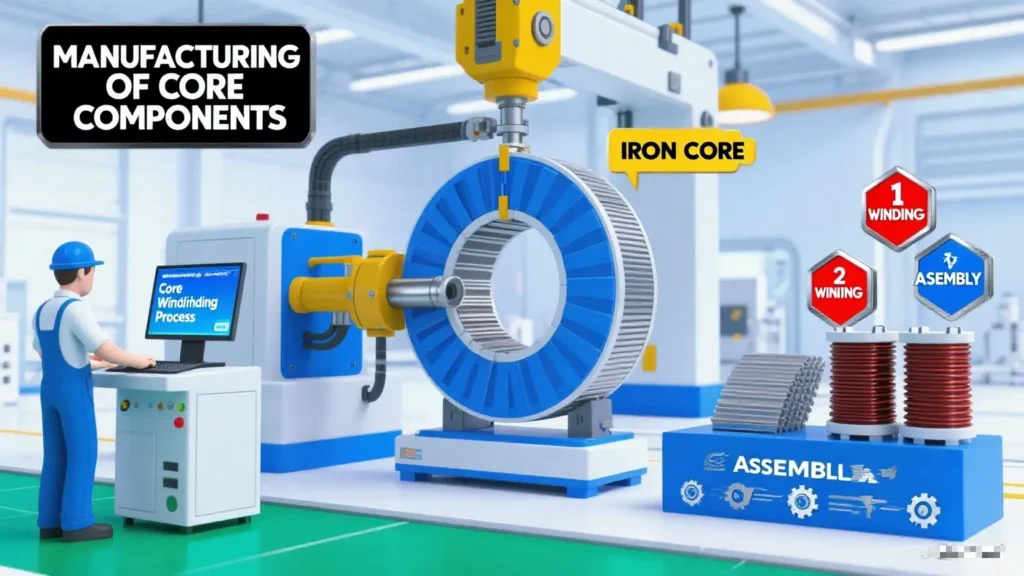
2.Iron Core Inspection: Grounding Resistance Measurement
3.Insulating Oil Inspection
①Breakdown Voltage Test
②Acid Value Test
③Moisture Content Test
4.Tap Changer Inspection
①Operational Performance Check
②Switching Time Measurement
5.Radiator Inspection
①Appearance and Operation Check
②Infrared Thermographic Detection
6.Protection Device Inspection
①Action Calibration of Gas Relay
②Inspection of Other Protection Devices
1.Establishment of Neutral Point
In power systems with ungrounded neutral points (such as 10kV and 35kV distribution networks), three-phase lines do not have a natural neutral point, making it impossible to directly implement grounding protection. A grounding transformers artificially draws out a neutral point through special wiring (e.g., star-open delta connection), providing a connection point for neutral grounding devices (such as arc suppression coils and resistors).
2.Fault Protection Support
When a single-phase ground fault occurs in the system, the grounding transformers can limit the fault current within a safe range. At the same time, it cooperates with relay protection devices to quickly detect the fault and trip, preventing the fault from expanding.
3.Voltage Measurement and Monitoring
Its open delta winding can be connected to a voltage transformer to monitor the system’s zero-sequence voltage, which is used to determine the type and location of ground faults.
Ⅱ.Product Advantages
Oil-immersed grounding transformers demonstrate targeted advantages in specific application scenarios, as detailed below:
1.Stronger Functional Adaptability, Specifically Designed for Grounding Protection
①Precisely Establishing Zero-Sequence Current Path
Oil-immersed grounding transformers specifically construct a low-impedance zero-sequence path through special winding connections. This ensures that zero-sequence current can flow stably when a single-phase ground fault occurs in the system, providing accurate fault signals for relay protection devices.
②Deep Compatibility with Grounding System Protection Devices
Oil-immersed grounding transformers can be directly connected in series with arc suppression coils to compensate for grounding capacitive current by adjusting inductance and extinguish fault arcs; or connected in series with grounding resistors to limit the grounding current within a safe range and prevent fault expansion. This compatibility is a “customized advantage” that distribution transformers do not possess.
2.More Efficient Structural Design, Optimized Space and Cost
①Small Capacity with High Cost-Effectiveness, Avoiding Functional Redundancy
During normal operation, oil-immersed grounding transformers only carry extremely small no-load current or zero-sequence current. Their rated capacity is usually 1/10 to 1/5 that of distribution transformers.
②Integrated Design, Meeting Multiple Needs Simultaneously
Oil-immersed grounding transformers can be designed as an integrated “grounding + station service transformer” structure. This design eliminates the need for additional station service transformers, saving equipment procurement costs and installation space.
3.Operational Characteristics Better Adapted to Fault Scenarios, with Higher Stability
①Stable Zero-Sequence Impedance Characteristics, Ensuring Protection Accuracy
Through special winding design, oil-immersed grounding transformers achieve stable zero-sequence impedance with high linearity, ensuring accurate operation of protection devices.
②Stronger Short-Term Impact Resistance
The windings and insulation systems of oil-immersed grounding transformers are specially optimized for short-term fault current impacts. They have larger thermal capacity, enabling them to withstand high current impacts before fault clearance (usually < 10 seconds). Their mechanical strength (resistance to short-circuit electromagnetic forces) is also superior, reducing the risk of fault expansion.
4.More Flexible Environmental and Maintenance Adaptability
①Environmental Adaptability Comparable to Distribution Transformers, but with More Focused Functional Scenarios
Due to their small capacity and low heat generation, oil-immersed grounding transformers exhibit better heat dissipation performance in enclosed cabinets or narrow spaces.
②Maintenance Costs Comparable, but Higher Functional Value Throughout the Lifecycle
If ordinary distribution transformers are used to replace grounding transformers, additional grounding devices (such as arc suppression coils and grounding resistance cabinets) must be configured. This not only increases costs but may also reduce system reliability due to compatibility issues, resulting in higher long-term comprehensive costs.
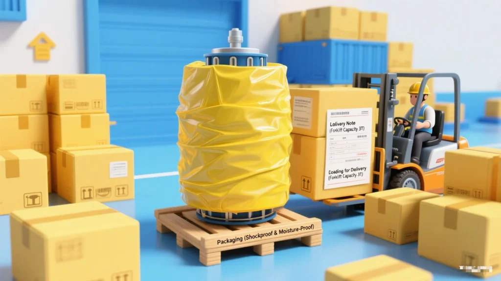
Ⅳ.Packaging and Delivery
1.The inside of the oil tank is filled with transformer oil (oil level up to 2/3 of the tank height), and all interfaces are sealed.
2.Vulnerable components such as bushings and terminals are equipped with protective covers, and the whole unit is fixed on a transport frame.
3.Accompanying technical documents: factory test report, certificate of conformity, installation manual, list of spare parts, etc.
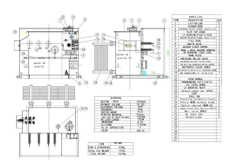
Diagram
Yes, it can be flexibly matched with both systems. When used in a resonant grounding system, it coordinates with arc suppression coils to extinguish ground fault arcs; when used in a resistance grounding system, it works with neutral grounding resistors to limit fault current, meeting the grounding protection requirements of different 35kV power grids.
Q:How to confirm that the 35kV Oil-immersed Grounding Transformer matches the ambient conditions of the installation site?
A:Focus on three key environmental indicators: first, the ambient temperature range, generally requiring adaptation to -40℃ to +40℃; second, the altitude, with most products suitable for areas below 1000m (derating is required for high-altitude areas); third, the pollution level, selecting corresponding anti-pollution coating tanks for coastal, chemical or dusty areas.
Q:Can the tank of 35kV Oil-immersed Grounding Transformers be customized for special scenarios?
A:Yes, customization is supported. For coastal areas with high salt spray, anti-corrosion alloy tanks or heavy-duty anti-rust coating tanks can be customized; for mining areas with frequent vibrations, shock-absorbing base structures can be added; for areas with strict noise requirements, low-noise tank designs with sound insulation layers are available.
The comprehensive protection configuration of the Kete earthing transformer serves as the “first line of defense”, effectively preventing faults that the transformer may encounter during operation, such as short circuits (e.g., inter-turn short circuits of windings, short circuits to ground), overloading, and excessive oil temperature.
①Electrical Protection
·Current quick-break protection: Designed to handle severe short-circuit faults.
·Overcurrent protection: Addresses general short-circuit faults or overloading issues.
·Zero-sequence current protection: Targets faults in the grounding system.
When triggered, these protection mechanisms can quickly initiate tripping or issue alarms.
②Non-Electrical Protection
·Oil temperature protection: Triggers an alarm or tripping when the top-layer oil temperature exceeds the safe threshold.
·Oil level protection: Issues an alarm when the oil level is too low or too high, preventing insufficient insulating oil or tank deformation.
·Gas protection (Buchholz protection): Activates an alarm or tripping when gas is generated inside the tank, responding to minor internal faults or severe short circuits.
③Accuracy of Protection Settings
Protection settings are calibrated based on transformer parameters (e.g., rated current, short-circuit current) and system requirements. This calibration prevents “maloperation” (tripping during normal operation) or “failure to operate” (no response when a fault occurs).
The choice between ONAN (Oil Natural Circulation and Air Natural Cooling) and ONAF (Oil Natural Circulation and Air Forced Cooling) cooling methods for Kete oil-immersed grounding transformers is corely based on the matching between the transformer’s heat dissipation requirements and actual heat dissipation conditions. Specifically, it can be comprehensively judged from the following 5 key dimensions:
①Transformer Rated Capacity and Heat Generation from Losses
This is the most fundamental basis. The heat generated by a transformer mainly comes from copper losses (load losses) and iron losses (no-load losses). The larger the capacity, the higher the losses and the stronger the heat dissipation demand:
·Small-capacity transformers (low loss):
When the rated capacity is small (e.g., ≤500kVA for 10kV class, ≤1000kVA for 35kV class), the heat generated by losses is small. Heat can be dissipated through the natural convection of transformer oil (hot oil rises, cold oil falls) and the natural convection between the casing/radiator and air, without the need for additional cooling equipment. Therefore, ONAN is preferred.
·Medium and large-capacity transformers (high loss):
When the capacity exceeds the above range (e.g., ≥800kVA for 10kV class, ≥1600kVA for 35kV class), losses increase significantly, and the natural heat dissipation rate cannot match the heat generation. This may cause the oil temperature to exceed national standard limits (usually top oil temperature rise ≤55K or 60K). In such cases, fans must be used to force air flow and accelerate heat dissipation, so ONAF is chosen.
②Operating Load Characteristics
The actual load rate and operation mode of the transformer directly affect heat dissipation requirements:
·Low load rate or intermittent operation:
If the transformer operates at light load for a long time (load rate < 50%) or only runs during short-term peak periods (e.g., rural distribution transformers), even if its capacity is slightly larger, the actual heat generation is low. The natural heat dissipation capacity of ONAN can meet the demand, and there is no need to waste energy on fans. Thus, ONAN is selected.
·High load rate or continuous full-load operation:
For transformers in industrial parks, urban core distribution networks, and other equipment that operate at full load for a long time or have large load fluctuations (needing to cope with short-term overload), heat generation remains high. ONAN cannot meet the heat dissipation requirements, so ONAF’s forced air cooling via fans is necessary. Even during overload, fans can enhance heat dissipation capacity (usually supporting 10%-20% short-term overload). Hence, ONAF is chosen.
③Installation Environment and Heat Dissipation Conditions
Environmental factors directly affect the efficiency of natural heat dissipation, and cooling methods need to be adjusted according to scenarios:
·Well-ventilated and low-temperature environments:
If the transformer is installed in an open outdoor area, high-altitude regions (low air density but good ventilation), or cold areas, the efficiency of natural convection heat dissipation is high. Even if the capacity is close to the critical value, ONAN can be prioritized.
·Poorly ventilated and high-temperature environments:
④Cost and Maintenance Requirements
maintenance costs almost zero. It is suitable for scenarios sensitive to cost and with limited maintenance resources (e.g., rural power grids, small user transformers).
Kete oil-immersed grounding transformers mainly adopt two common cooling methods: ONAN and ONAF.
①Scope of Application of ONAN
·Transformers with small capacity
Typical applicable capacity: Usually used for transformers of 10kV class with 500kVA and below, and 35kV class with 1000kVA and below.
Reason: Small-capacity transformers have low losses (small heat generation), and natural heat dissipation can meet the temperature rise requirements, with a simple structure and low cost.
·Scenarios with loose installation environment
Suitable for outdoor open spaces, well-ventilated indoor distribution rooms, or areas with low ambient temperatures.
If installed in enclosed spaces (such as basements), additional evaluation of heat dissipation conditions is required, and the cooling method may need to be upgraded.
·Transformers with low load rate or intermittent operation
For transformers that are in a light load state for a long time (load rate < 50%), the heat dissipation capacity of ONAN is sufficient, without wasting energy consumption from forced cooling.
②Scope of Application of ONAF
·Medium and large capacity transformers
Typical applicable capacity: 10kV class with 800kVA and above, 35kV class with 1600kVA and above for small and medium-sized transformers.
Reason: Medium and large-capacity transformers have high losses (large copper loss and iron loss), and natural heat dissipation cannot meet the temperature rise limit, so fans are needed to assist in enhancing heat dissipation.
·Transformers with high load rate or continuous operation
Suitable for scenarios with long-term full-load operation or large load fluctuations (needing to cope with short-term overload), such as main transformers in industrial plants and hub transformers in urban distribution networks.
·Environments with limited heat dissipation conditions
If the transformer is installed in a poorly ventilated indoor environment or in areas with high ambient temperatures (such as tropical regions), ONAF can make up for the deficiency of natural heat dissipation through forced air cooling, avoiding excessive oil temperature that affects service life.
Related Products
-
Three Phase Zig-Zag Transformer Original manufacturer-10kV 10.5kV 11kV
-
17.5kV 20kV Three-phase oil-immersed grounding transformer with oil conservator
-
Customization 33kV 34.5kV 35kV oil-immersed grounding transformer
-
Zig Zag Grounding Transformers up to 46kV
-
Zig-Zag Neutral Grounding Transformers manufactures-30kV 45kV 72.5kV
-
Oil immersed neutral earthing transformer Manufacturers 27kV 33kV 34.5kV 35kV
-
Tailored advanced oil immersed neutral grounding transformer 35kV 36kV 44kV
-
Zig-Zag Liquid Filled Pad Mounted Grounding Transformer 30kV 33kV 34.5kV
-
CSA ANSI/IEEE Standards Pad Mounted Zig Zag Grounding Transformer
-
35KV 100A Zig Zag Pad Mounted Grounding Transformer