Three phase Three-winding Auto Transformer 330kV 360MVA
| Brand | Vziman |
| Model NO. | Three phase Three-winding Auto Transformer 330kV 360MVA |
| Rated capacity | 180000kVA |
| No-load loss | 64kW |
| Series | OSFPSZ22 |
Three-phase Auto Transformer Product Description
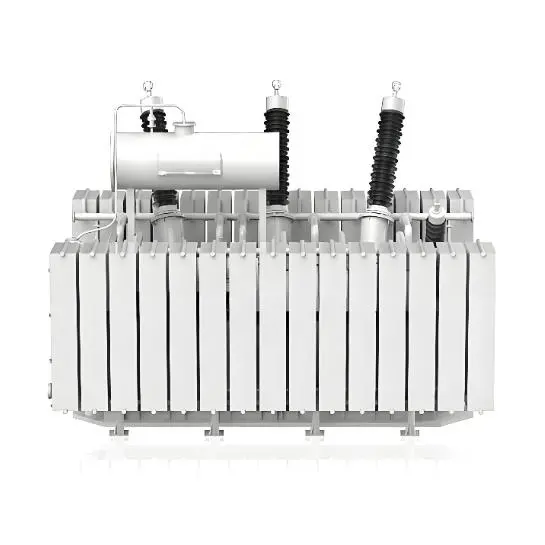
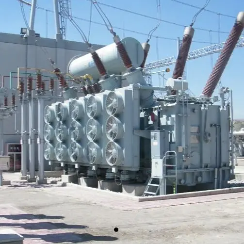
Our Three-phase Auto Transformer is a high-performance power equipment engineered for ultra-high voltage power transmission and distribution systems, perfectly compatible with the operational demands of Extra High Voltage Transformers in large-scale power grids. This three-phase three-winding auto-transformer integrates advanced winding design and high-grade insulating materials, realizing efficient voltage transformation, stable power transmission and low-loss operation, and its structural optimization makes it more adaptable to the compact layout requirements of Extra High Voltage Transformers in hub substations and power transmission projects. The Three-phase Auto Transformer boasts excellent load adaptability and grid compatibility, can effectively suppress grid harmonics and voltage fluctuations, and is a core supporting equipment for Extra High Voltage Transformers in cross-regional power grid interconnection, new energy power transmission and large industrial power supply scenarios, providing reliable technical support for the safe and efficient operation of ultra-high voltage power systems.
Three-phase Auto Transformer Core Features
- High-efficiency Voltage Transformation & Low Loss:The Three-phase Auto Transformer adopts an optimized three-winding topological structure, with voltage transformation efficiency reaching over 99.5%, significantly reducing power transmission losses; it is matched with the low-loss design standard of Extra High Voltage Transformers, further improving the overall energy efficiency of the ultra-high voltage power grid.
- Compact Structure & Space-saving:Integrating integrated winding and modular assembly process, the Three-phase Auto Transformer has a more compact volume under the same power rating, perfectly adapting to the limited installation space of Extra High Voltage Transformers in substation engineering and greatly saving the overall construction space of power transmission projects.
- Strong Grid Adaptability & Stable Operation:The Three-phase Auto Transformer is equipped with advanced fault resistance and voltage regulation functions, which can adapt to the complex working conditions of ultra-high voltage power grids and effectively cope with grid load fluctuations; it forms a stable operation system with Extra High Voltage Transformers, enhancing the anti-interference ability and operation reliability of the whole power transmission system.
- High Insulation Performance & Long Service Life:Adopting high-strength environmental protection insulating materials and multi-layer insulation structure design, the Three-phase Auto Transformer meets the strict insulation requirements of Extra High Voltage Transformers, can withstand ultra-high voltage impact and long-term operation aging, and its core components have passed rigorous durability testing, effectively extending the equipment's fault-free operation cycle.
(1) 330kV 90000kVA~720000kVA Three-phase Double-winding Power Transformer with Off-circuit Tap-changer
| Rated capacity (kVA) | Voltage combination and tapping range | Vector group | Energy consumption class I | Energy consumption class II | Energy consumption class III | Short-circuit impedance (%) | ||||
| HV tapping range (%) | LV (kV) | No-load loss (kW) | On-load loss (kW) | No-load loss (kW) | On-load loss (kW) | No-load loss (kW) | On-load loss (kW) | |||
| 90000 |
345 345±2×2.5% 363±2×2.5% |
10.5 13.8 15.75 18 20 |
YNd11 | 37 | 247 | 44 | 247 | 54 | 260 | 14~15 |
| 120000 | 47 | 305 | 55 | 305 | 68 | 323 | ||||
| 150000 | 56 | 362 | 66 | 362 | 81 | 382 | ||||
| 180000 | 64 | 415 | 75 | 415 | 93 | 438 | ||||
| 240000 | 80 | 515 | 94 | 515 | 116 | 543 | ||||
| 360000 | 109 | 722 | 129 | 722 | 158 | 762 | ||||
| 370000 | 111 | 736 | 131 | 736 | 162 | 777 | ||||
| 400000 | 118 | 780 | 139 | 780 | 171 | 824 | ||||
| 720000 | 183 | 1212 | 216 | 1212 | 266 | 1280 | ||||
Note: Transformers with various special parameters and performance can be manufactured according to customer requirements.
(2) 330kV 90000kVA~240000kVA Three-phase Three-winding Power Transformer with Off-circuit Tap-changer
| Rated capacity (kVA) | Voltage combination and tapping range | Vector group | Energy consumption class I | Energy consumption class II | Energy consumption class III |
Short-circuit impedance (%) |
Capacity assignment (%) | |||||
| HV tapping range (%) | MV(kV) | LV (kV) | No-load loss (kW) | On-load loss (kW) | No-load loss (kW) | On-load loss (kW) | No-load loss (kW) | On-load loss (kW) | ||||
| 90000 |
330±2×2.5% 345±2×2.5% |
121 |
10.5 13.8 15.75 |
YN yn0d11 |
42 | 302 | 50 | 302 | 62 | 318 |
HV-MV: 24~26 HV-LV: 14~15 MV-LV: 8~9 |
100/100/100 |
| 120000 | 53 | 372 | 62 | 372 | 77 | 394 | ||||||
| 150000 | 63 | 442 | 74 | 442 | 92 | 466 | ||||||
| 180000 | 72 | 507 | 85 | 507 | 104 | 535 | ||||||
| 240000 | 89 | 629 | 105 | 629 | 130 | 664 | ||||||
Note:
- The data in the above sheet are applicable to step-up transformer.
- The capacity allocation of the step-up type can also be (100/50/100)%.
- Step-down type transformer can be provided as required, its short circuit impedance: HV-LV 24%~26%, HV-MV 14%~15%, MV-LV 8%~9%, and its capacity can be (100/100/50)% or (100/50/100)%.
- Short circuit impedance in the sheet is based on 100% rated capacity.
- Transformers with various special parameters and performance can be manufactured according to customer requirements.
(3) 330kV 90000kVA~360000kVA Three-phase Three-winding Autotransformer with Off-circuit Tap-changer (Regulating in Series Winding)
| Rated capacity (kVA) | Voltage combination and tapping range | Vector group | Energy consumption class I | Energy consumption class II | Energy consumption class III |
Short-circuit impedance (%) |
Capacity assignment (%) | |||||
| HV tapping range (%) | MV(kV) | LV (kV) | No-load loss (kW) | On-load loss (kW) | No-load loss (kW) | On-load loss (kW) | No-load loss (kW) | On-load loss (kW) | ||||
| 90000 |
330±8×2.5% 345±8×2.5%
|
121
|
10.5 11 35 38.5
|
YN a0d11
|
25 | 237 | 29 | 237 | 36 | 250 |
HV-MV: 10 ~ 11 HV-LV: 24 ~ 26 MV-LV: 12 ~ 14 |
100/100/30 |
| 120000 | 31 | 292 | 36 | 292 | 45 | 308 | ||||||
| 150000 | 37 | 347 | 44 | 347 | 54 | 366 | ||||||
| 180000 | 42 | 396 | 50 | 396 | 62 | 418 | ||||||
| 240000 | 53 | 492 | 62 | 492 | 77 | 520 | ||||||
| 360000 | 72 | 668 | 85 | 668 | 104 | 705 | ||||||
Note:
- The data in the above sheet are applicable to step-down type transformer.
- The step-up type transformer can be provided as required, and its short circuit impedance: HV-LV 10%~11%, HV-MV 24%~26%, MV-LV 12%~14%.
- Short circuit impedance in the sheet is based on 100% rated capacity.
- Transformers with various special parameters and performance can be manufactured according to customer requirements.
(4) 330kV 90000kVA~360000kVA Three-phase Three-winding Autotransformer with On-load Tap-changer (Regulating at the End of Series Winding)
| Rated capacity (kVA) | Voltage combination and tapping range | Vector group | Energy consumption class I | Energy consumption class II | Energy consumption class III |
Short-circuit impedance (%) |
Capacity assignment (%) | |||||
| HV tapping range (%) | MV(kV) | LV (kV) | No-load loss (kW) | On-load loss (kW) | No-load loss (kW) | On-load loss (kW) | No-load loss (kW) | On-load loss (kW) | ||||
| 90000 |
330±2×2.5%
|
121
|
10.5 11 35 38.5
|
YN a0d11
|
26 | 235 | 31 | 235 | 38 | 248 |
HV-MV: 10 ~ 11 HV-LV: 24 ~ 26 MV-LV: 12 ~ 14 |
100/100/30 |
| 120000 | 32 | 292 | 38 | 292 | 47 | 308 | ||||||
| 150000 | 38 | 345 | 45 | 345 | 55 | 364 | ||||||
| 180000 | 43 | 396 | 51 | 396 | 63 | 418 | ||||||
| 240000 | 54 | 492 | 64 | 492 | 79 | 520 | ||||||
| 360000 | 74 | 668 | 87 | 668 | 107 | 705 | ||||||
Note:
- The data in the above sheet are applicable to step-down type transformer. Step-up type transformer can be provided as required.
- Short circuit impedance in the sheet is the value based on 100% rated capacity.
- Transformers with various special parameters and performance can be manufactured according to customer requirements.
(5) 330kV 90000kVA~360000kVA Three-phase Three-winding Autotransformer with On-load Tap-changer (Regulating at MV 110kV Line End Side)
| Rated capacity (kVA) | Voltage combination and tapping range | Vector group | Energy consumption class I | Energy consumption class II | Energy consumption class III |
Short-circuit impedance (%) |
Capacity assignment (%) | |||||
| HV tapping range (%) | MV(kV) | LV (kV) | No-load loss (kW) | On-load loss (kW) | No-load loss (kW) | On-load loss (kW) | No-load loss (kW) | On-load loss (kW) | ||||
| 90000 |
330 345
|
121±8×1.25%
|
10.5 11 35 38.5
|
YN a0d11
|
27 | 251 | 32 | 251 | 39 | 265 |
HV-MV: 10 ~ 11 HV-LV: 26 ~ 28 MV-LV: 16 ~ 17 |
100/100/30 |
| 120000 | 34 | 311 | 40 | 311 | 49 | 329 | ||||||
| 150000 | 40 | 369 | 47 | 369 | 58 | 390 | ||||||
| 180000 | 46 | 423 | 54 | 423 | 66 | 447 | ||||||
| 240000 | 56 | 526 | 66 | 526 | 82 | 555 | ||||||
| 360000 | 76 | 713 | 90 | 713 | 111 | 752 | ||||||
Note:
- The data in the above sheet are applicable to step-down type transformer. Step-up type transformer can be provided as required.
- Short circuit impedance in the sheet is the value based on 100% rated capacity.
- Transformers with various special parameters and performance can be manufactured according to customer requirements.
(6) 330kV 90000kVA~360000kVA Three-phase Three-winding Autotransformer with Off-circuit Tap-changer (Regulating at MV 220kV line end side)
| Rated capacity (kVA) | Voltage combination and tapping range | Vector group | Energy consumption class I | Energy consumption class II | Energy consumption class III |
Short-circuit impedance (%) |
Capacity assignment (%) | |||||
| HV tapping range (%) | MV(kV) | LV (kV) | No-load loss (kW) | On-load loss (kW) | No-load loss (kW) | On-load loss (kW) | No-load loss (kW) | On-load loss (kW) | ||||
| 90000 |
330 345
|
121
|
10.5 11 35 38.5
|
YN a0d11
|
13 | 264 | 15 | 264 | 18 | 278 |
HV-MV: 10 ~ 11 |
100/100/30 |
| 120000 | 16 | 327 | 19 | 327 | 23 | 345 | ||||||
| 150000 | 19 | 338 | 22 | 338 | 27 | 409 | ||||||
| 180000 | 21 | 445 | 25 | 445 | 31 | 469 | ||||||
| 240000 | 27 | 553 | 32 | 553 | 39 | 582 | ||||||
| 360000 | 37 | 752 | 44 | 752 | 54 | 794 | ||||||
Note:
- The data in the sheet above are applicable to step-down type transformer. Step-up type transformer can be provided as required.
- Short circuit impedance in the sheet is the value based on 100% rated capacity.
- Short circuit impedance for HV-MV and MV-LV shall be agreed by the manufacturer and the user.
- Transformers with various special parameters and performance can be manufactured according to customer requirements.
(7) 330kV 90000kVA~360000kVA, Three-phase, Three-winding Autotransformer with On-load Tap-changer (Regulating at MV 220kV line end side)
| Rated capacity (kVA) | Voltage combination and tapping range | Vector group | Energy consumption class I | Energy consumption class II | Energy consumption class III |
Short-circuit impedance (%) |
Capacity assignment (%) | |||||
| HV tapping range (%) | MV(kV) | LV (kV) | No-load loss (kW) | On-load loss (kW) | No-load loss (kW) | On-load loss (kW) | No-load loss (kW) | On-load loss (kW) | ||||
| 90000 |
330 345 363
|
230±4×1.25% 230±8×1.25% 242±4×1.25% 242±8×1.25%
|
10.5 11 35 38.5
|
YN a0d11
|
14 | 264 | 16 | 264 | 20 | 278 |
HV-MV: 10 ~ 11 |
100/100/30 |
| 120000 | 17 | 327 | 20 | 327 | 25 | 345 | ||||||
| 150000 | 20 | 338 | 24 | 338 | 30 | 409 | ||||||
| 180000 | 23 | 445 | 27 | 445 | 34 | 469 | ||||||
| 240000 | 29 | 553 | 34 | 553 | 42 | 582 | ||||||
| 360000 | 40 | 753 | 47 | 753 | 58 | 795 | ||||||
Note:
- The data in the sheet above are applicable to step-down type transformer. Step-up type transformer can be provided as required.
- Short circuit impedance in the sheet is the value based on 100% rated capacity.
- Short circuit impedance for HV-MV and MV-LV shall be agreed by the manufacturer and the user.
- Transformers with various special parameters and performance can be manufactured according to customer requirements.
Three-phase Auto Transformer Application Scenarios
- Cross-regional Ultra-high Voltage Power Grid Interconnection:Deployed in inter-provincial and cross-regional hub substations, the Three-phase Auto Transformer undertakes the core voltage transformation and power regulation tasks of ultra-high voltage power transmission, and is used in conjunction with Extra High Voltage Transformers to realize the optimal allocation of cross-regional power resources and enhance the interconnection capacity of the national power grid.
- Large-scale New Energy Base Power Transmission:Applied in the power transmission systems of wind-solar hybrid bases, large hydropower stations and pumped storage power stations, the Three-phase Auto Transformer boosts the new energy power to the ultra-high voltage level for long-distance transmission, and matches with Extra High Voltage Transformers to ensure low-loss and high-efficiency grid connection of clean energy.
- Large-scale Industrial and Mining Enterprise Ultra-high Voltage Power Supply:Used in the core power supply systems of large petrochemical, non-ferrous metal smelting and heavy manufacturing enterprises, the Three-phase Auto Transformer provides stable and high-quality ultra-high voltage power support for high-power production equipment, and is compatible with Extra High Voltage Transformers to meet the strict requirements of industrial production for power continuity and voltage stability.
- Urban Core Power Grid Upgrading and Reconstruction:Applied in the upgrading and expansion projects of urban central ultra-high voltage substations, the Three-phase Auto Transformer adapts to the increasing power load demand of urban core areas, and is combined with Extra High Voltage Transformers to optimize the urban power grid structure and improve the power supply capacity and reliability of the core urban area.
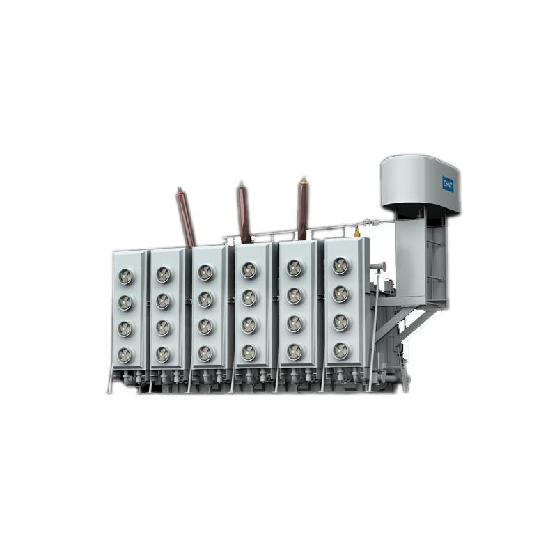
The Three-phase Auto Transformer features a specialized three-winding topological structure, different from traditional two-winding transformers, it shares a common winding between the primary and secondary sides, which greatly improves voltage transformation efficiency and reduces equipment volume and weight under the same power rating. This structural design of the Three-phase Auto Transformer also enhances its power regulation flexibility, can realize multi-voltage grade output, and is more adaptable to the diverse voltage matching needs of power grid transmission and distribution systems, while the integrated winding process further boosts the structural stability and operation reliability of the Three-phase Auto Transformer.